- 1 General description
- 2 Production process
- 3 Types of map
- 3.1 Full-mission, full-channel maps (7 HFI, 4 LFI)
- 3.2 Full mission light maps, full channel maps (7 HFI, 7 LFI)
- 3.3 Single-survey, full-channel maps (35 LFI)
- 3.4 Year maps, full-channel maps (16 LFI)
- 3.5 Half-mission maps, full-channel maps (14 HFI, 12 LFI)
- 3.6 Full mission, single-detector maps (22 LFI)
- 3.7 Full-mission, detector-set or detector-pairs maps (8 LFI)
- 3.8 Half-ring maps (62 LFI)
- 3.9 Caveats and known issues
- 4 Inputs
- 5 Related products
- 6 File names
- 7 FITS file structure
- 8 Polarization convention used in the Planck project
- 9 References
- 10 Other releases: 2020-NPIPE, 2015 and 2013
- 11 References
General description[edit]
Sky maps give the best estimate of the intensity and polarization (Stokes Q and U components), if available, of the signal from the sky after removal, as far as possible, of known systematic effects (mostly instrumental, but including also the solar and Earth-motion dipoles, Galactic stray light, and the zodiacal light). The Planck Collaboration has made three releases of maps, in 2013, 2015 and 2018. This section describes the 2018 release. For descriptions of the other two releases, please go to the sections at the end of this chapter related to 2013 and 2015.
In the 2013, 2015 and 2018 releases, sky maps are provided for the full Planck mission using all valid detectors in each frequency channel, and also for various subsets obtained by splitting the mission into various time ranges or into subsets of the detectors in a given channel, or by considering only odd or even pointing periods. These products are especially interesting for characterization purposes (see also the data validation section), though some are also useful for the study of source variability. The details of the start and end of the time ranges are given in the table below.
For this (2018) release, HFI is providing a more limited subset of maps that include the full channel maps, the half-mission and the odd-even ring splits. Also, note that for the 353 GHz band, both full channel and PSBs only maps are provided, and that by default it is the PBS-only maps that are served.
Ranges for mission and surveys
| Range |
ODs |
HFI rings |
pointing-IDs |
Comment
|
|---|
| Nominal mission |
91 - 563 |
240 - 14723 |
00004200 - 03180200 |
|
| Full mission |
91 - 974 |
240 - 27005 |
00004200 - 05322620 |
For HFI
|
| Full mission |
91 - 1543 |
n/a |
00004200 - 06511160 |
For LFI
|
| Survey 1 |
91 - 270 |
240 - 5720 |
00004200 - 01059820 |
|
| Survey 2 |
270 - 456 |
5721 - 11194 |
01059830 - 02114520 |
|
| Survey 3 |
456 - 636 |
11195 - 16691 |
02114530 - 03193660 |
|
| Survey 4 |
636 - 807 |
16692 - 21720 |
03193670 - 04243900 |
|
| Survey 5 |
807 - 974 |
21721 - 26050 |
05267180 - 05322590 |
End of mission for HFI
|
| Survey 5 |
807 - 993 |
n/a |
05267180 - 06344800 |
End of survey for LFI
|
| Survey 6 |
993 - 1177 |
n/a |
06344810 - 06398120 |
LFI only
|
| Survey 7 |
1177 - 1358 |
n/a |
06398130 - 06456410 |
LFI only
|
| Survey 8 |
1358 - 1543 |
n/a |
06456420 - 06511160 |
LFI only
|
| HFI mission-half-1 |
91 - 531 |
240 - 13471 |
00004200 - 03155580 |
|
| HFI mission-half-2 |
531 - 974 |
13472 - 27005 |
03155590 - 05322590 |
|
| LFI Year 1 |
91 - 456 |
n/a |
00004200 - 02114520 |
|
| LFI Year 2 |
456 - 807 |
n/a |
02114530 - 04243900 |
|
| LFI Year 3 |
807 - 1177 |
n/a |
05267180 - 06398120 |
|
| LFI Year 4 |
1177 - 1543 |
n/a |
06398130 - 06511160 |
|
To help in further processing, there are also masks of the Galactic plane and of point sources, each provided for several different depths.
All sky maps are in HEALPix format, with Nside=1024 (for LFI 30, 44, and 70GHz) and 2048 (for LFI 70GHz and HFI), in Galactic coordinates, and with nested ordering.
WARNING: The HEALPix convention for polarization is not the same as the IAU convention (Section 8 on this page).
The signal is given in units of KCMB for 30 to 353 GHz, and of MJy.sr-1 (for a constant νIν energy distribution) for 545 and 857 GHz. For each frequency channel, the intensity and polarization maps are packaged into a "BINTABLE" extension of a FITS file together with a hit-counts map (or "hits map", for short, giving the number of observation samples that are accumulated in a pixel, all detectors combined) and with the variance and covariance maps. Additional information is given in the FITS file header. The structure of the FITS file is given in the FITS file structure section below.
Production process[edit]
Sky maps are produced by appropriately combining the data from all working detectors in a frequency channel over some period of the mission. They give the best estimate of the signal from the sky (unpolarized) after removal, as far as possible, of known systematic effects and of the dipole signals induced by the motion of the solar system in the CMB and of the Planck satellite in the solar system. In particular, they include the zodiacal light emission ("zodi" for short) and also the scattering from the far sidelobes of the beams (FSL). More on this below.
HFI processing[edit]
The mapmaking and calibration process is described in detail in the mapmaking section and in the Planck-2016-XLVI[1] paper, where detailed references can be found. In brief, the timelines are cleaned and calibrated and converted into HealPix rings (HPRs), then SRoll is applied to destripe them in polarised space (removal of very low frequency noise by minimising differences at ring crossing points), to remove knows systematic effects (including the flux calibration), and to project them onto a HealPix map.
The processing yields maps of the signal, hit counts and auto- and cross-variance maps for the 6 full channel and for a pseudo-channel built from the 353 PSBs only. For each channel HFI provides
- a map for the full mission
- two maps for each half-mission
- two maps for built from odd or even rings only
for a total of 35 maps.
PR3 HFI products[edit]
Healpix Pixel Rings (HPRs)[edit]
SRoll main products are the HFI frequency maps. Nevertheless, we also make available the Healpix Pixel Rings (HPRs) of those maps, ie. the data before projection. See description of those files.
Frequency maps[edit]
The 35 HFI frequency maps of the PR3 Legacy Release are the followings:
PR3 HFI frequency maps
|
|
100 GHz
|
143 GHz
|
217 GHz
|
353 GHz
|
353_PSB GHz
|
545 GHz
|
857 GHz
|
|---|
| Full mission
|
I, Q, U
|
I, Q, U
|
I, Q, U
|
I, Q, U
|
I, Q, U
|
I
|
I
|
| Half mission 1
|
I, Q, U
|
I, Q, U
|
I, Q, U
|
I, Q, U
|
I, Q, U
|
I
|
I
|
| Half mission 2
|
I, Q, U
|
I, Q, U
|
I, Q, U
|
I, Q, U
|
I, Q, U
|
I
|
I
|
| Odd rings
|
I, Q, U
|
I, Q, U
|
I, Q, U
|
I, Q, U
|
I, Q, U
|
I
|
I
|
| Even rings
|
I, Q, U
|
I, Q, U
|
I, Q, U
|
I, Q, U
|
I, Q, U
|
I
|
I
|
See description of those files. These maps are available on the [Planck Legacy Archive].
LFI processing[edit]
LFI maps were constructed with the MADAM mapmaking code, version 3.7.4. The code is based on a generalized destriping technique, where the correlated noise component is modelled as a sequence of constant offsets, called "baselines". A noise filter was used to constrain the baseline solution, allowing the use of 0.25-s and 1-s baselines for the 30 and 44GHz, and 70 GHz channels, respectively. See section 6 of Planck-2020-A2[2].
Radiometers were combined according to the horn-uniform weighting scheme to minimize systematics. The flagged samples were excluded from the analysis by setting their weights to Cw-1 = 0. The Galaxy region was masked out in the destriping phase, to reduce errors arising from strong signal gradients. The polarization component was included in the analysis.
- Dipole and Far Side Lobe correction
- Input timelines are cleaned by the 4π-convolved dipole and Galactic stray light, obtained as a convolution of the 4π in-band far sidelobes and Galactic simulations, as explained in Planck-2020-A2[2].
Scaling of the maps due to beam effects is taken into account in the LFI's beam functions (as provided in the RIMO) which should be used for analysis of diffuse components.
- Bandpass leakage correction
- LFI high-resolution maps have been reseleased corrected for bandpass leakage or uncorrected. Further details about the procedure used to generate the bandpass correction maps can be found in section 7 of Planck-2020-A2[2].
- Map zero-level
- The 30, 44 and 70 GHz, maps are corrected for a zero-level monopole by applying an offset correction (see the LFI Calibration paper, Planck-2015-A05[3]). Note that the offset applied is indicated in the header as a comment keyword.
A detailed description of the mapmaking procedure is given in Planck-2013-II[4], Planck-2015-A02[5], Planck-2015-A06[6] and in the Mapmaking section here, in Planck-2020-A2[2] only a summary is reported.
Types of map[edit]
Full-mission, full-channel maps (7 HFI, 4 LFI)[edit]
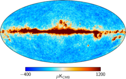
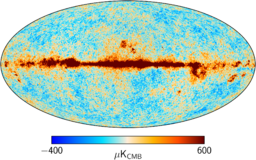
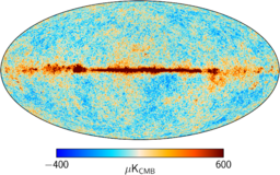
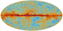
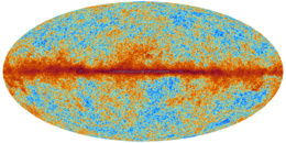
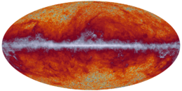
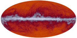
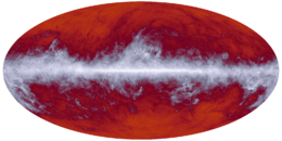
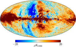
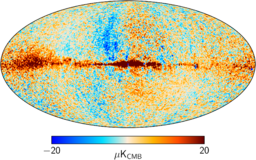
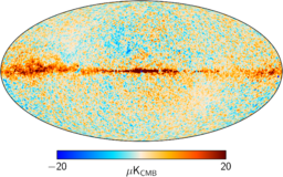
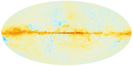
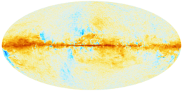
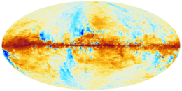
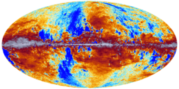
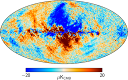
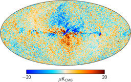
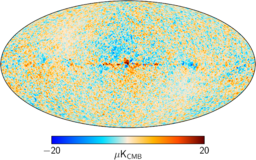
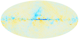
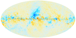
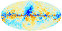
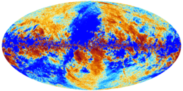
Full channel maps are built using all the valid detectors of a frequency channel and cover either the full or the nominal mission. For HFI, the 143-8 and 545-3 bolometers are rejected entirely, since they are seriously affected by RTS noise. HFI provides the Q and U components for the 100, 143, 217 and 353 GHz channels only. LFI provides the I, Q, and U maps for all the channels. Note that the HFI and LFI Q and U maps are corrected for bandpass leakage, version without correction for LFi is also provided. The I, Q, and U maps are displayed in the figures below. The colour range here is set using a histogram equalization scheme (from HEALPix) that is useful for these non-Gaussian data fields. For visualization purposes, the Q and U maps shown here have been smoothed with a 1° Gaussian kernel, otherwise they look like noise to the naked eye. The 70 GHz full map is also available at Nside=2048.
The high dynamic range colour scheme of the Planck maps is described here.
Full mission light maps, full channel maps (7 HFI, 7 LFI)[edit]
These maps are based on the Full mission maps but contain fewer columns, IQU from 30 to 353 GHz, and I only at 545 and 857 GHz. These maps have been produced to reduce the transfer time of the most downloaded frequency full mission maps.
Single-survey, full-channel maps (35 LFI)[edit]
Single-survey maps are built using all valid detectors of a frequency channel; they separately cover the different sky surveys. The surveys are defined as the times over which the satellite spin axis rotates by 180°, which, due to the position of the detectors in the focal plane does not cover the full sky, but a fraction between about 80% and 90%, depending on detector position. During adjacent surveys the sky is scanned in opposite directions (more precisely it is the ecliptic equator that is scanned in opposite directions). While these are useful to investigate variable sources, they are also used to study the systematics of the time-response of the detectors as they scan bright sources, like the Galactic Plane, in different directions during different survey. Note that the HFI and LFI missions cover five and eight surveys, respectively, and in the case of HFI the last survey in incomplete.
The 70 GHz survey maps are available also at Nside=2048. Note that LFI provides a special survey-map combination used in the low-ℓ analysis; this maps, available at the three LFI frequencies, 30, 44, and 70 GHz, was built using the combination of Surveys 1, 3, 5, 6, 7, and 8.
Year maps, full-channel maps (16 LFI)[edit]
These maps are built using the data of Surveys 1+2, Surveys 3+4, and so forth. They are used to study long-term systematic effects. The 70 GHz years maps are available also at Nside=2048.
Half-mission maps, full-channel maps (14 HFI, 12 LFI)[edit]
For HFI, the half mission is defined after eliminating those rings that are discarded for all bolometers, many of which occurred during the 5th survey when the "End-of-Life" tests were performed. The remaining rings are divided in half to define the two halves of the mission. This exercise is done for the full mission only.
For LFI, instead of the half-mission maps, the following year combinations have been created: Year 1+2, Year 1+3, Year 2+4, Year 3+4,
Full mission, single-detector maps (22 LFI)[edit]
For LFI, all the 22 Radiometers maps are available, and (obviously) only in Stokes I.
Full-mission, detector-set or detector-pairs maps (8 LFI)[edit]
The objective here is to build independent temperature (I) and polarization (Q and U) maps using the two pairs of polarization-sensitive detectors of each channel where they are available, i.e., for the 44-353 GHz channels. The table below indicates which detectors were used to build each detector set (detset).
Definition of LFI detector pairs
| Frequency |
Horn pair |
Comment
|
|---|
| 44 GHz |
24 |
This map is only in temperature
|
| 44 GHz |
25 and 26 |
|
| 70 GHz |
18 and 23 |
Available also at Nside=2048
|
| 70 GHz |
19 and 22 |
Available also at Nside=2048
|
| 70 GHz |
20 and 21 |
Available also at Nside=2048
|
Half-ring maps (62 LFI)[edit]
These maps are similar to the ones described above, but are built using only the first or the second halves of each ring (or pointing period). The HFI provides half-ring maps for the full mission only, as well as for the full channel, the detsets, and the single bolometers. The LFI provides half-ring maps for the full mission in each channel (70 GHz also at Nside=2048), for the full-mission radiometers, and for the full-mission horn pairs.
=== Odd and even rings maps (14 HFI)
As the name indicates, these are generated by using only the odd or only the even rings.
Caveats and known issues[edit]
HFI frequency maps[edit]
Some imperfections have shown up in the tests of the HFI PR3 maps that were previously hidden by higher-level systematics in the previous PR2 data. These lead to guidelines for the proper use of the HFI PR3 data. See Planck-2020-A3[7] for a detailed description of all these issues.
Update 12 Sep 2018: Covariance matrices in PR3.00 frequency maps FITS files were not correctly computed and contained wrong values. They must not be used for any purpose. These maps have been removed from the PLA. Version 3.01 must be used instead. Intensity, polarization and hit count maps have not changed.
Monopoles[edit]
Monopoles, which cannot be extracted from Planck data alone, are adjusted at each frequency (as was done in the previous PR2 release). For component separation, this provides maps that can be used directly in combination with other tracers. See Planck-2020-A3[7] for a detailed discussion.
In the 2018 maps, three monopoles have been adjusted:
- during production of the HFI frequency maps, an HI correlation analysis is carried out to adjust the overall monopole of the map to be consistent with the intensity of the Galactic dust foreground at high galactic latitudes (this adjustment was also done in the 2016 maps)
- a monopole corresponding to the zero-level of the CIB (Cosmic Infrared Background) estimated from a galaxy evolution model has been added to the maps (as for the 2016 maps)
- a monopole corresponding to the zero-level of zodiacal emission, representative of the high ecliptic latitude emission regions, has been added to the maps (note that this was not done in the 2016 maps).
It is recommended that for work separating CMB and diffuse Galactic components from HFI frequency maps, the CIB and Zodiacal emission monopoles should first be removed. Furthermore, especially for applications at low intensity, it is critical to appreciate that there are significant uncertainties in the zero levels in the Galactic maps. It is therefore also recommended that the maps be correlated with the HI map at high latitude, following the detailed methodology set out in Planck-2013-VIII[8] and [9]. Consideration should also be given to the possible effect of dust in the warm ionized medium, as discussed and quantified in [9].
Solar dipole residual[edit]
The Planck 2015 Solar dipole is removed from the PR3 HFI maps to be consistent with LFI maps and to facilitate comparison with the previous PR2 ones. The best Solar dipole determination from HFI PR3 data shows a small shift in direction of about 1', but a 1.8 μK lower amplitude. Removal of the Planck 2015 Solar dipole thus leaves a small but non-negligible dipole residual in the HFI PR3 maps. To correct for this, and adjust maps at the best photometric calibration, users of the HFI PR3 maps should:
- put back into the maps the Planck 2015 Solar dipole (d,l,b)= (3364.5 ± 2.0 μK, 264.00 ± 0.03°, 48.24 ± 0.02°),
- include the absolute calibration frequency bias, i.e., multiply by 1 minus the calibration bias,
- lastly, remove the HFI 2018 Solar dipole.
Use of the 353 GHz SWBs[edit]
In 2018, two types of maps at 353 GHz are provided, one including only PSBs and one including both PSBs and SWBs. For reasons detailed in Planck-2020-A3[7], it is recommended to use the former (i.e. only including PSBs). The alternative one including the 353 GHz SWBs should be used only for specific uses such as, for example, increasing the signal to noise level at high multipoles.
Color correction and component separation[edit]
In 2018 the SRoll algorithm has been used to produce the frequency maps. This algorithms adjusts by construction all single bolometer maps to the band average response. For this reason, it becomes impossible to use the different individual bolometer responses to extract foreground component maps, and the individual bolometer maps are not provided as part of the release. See Planck-2020-A3[7] for a detailed description. Note also that for the same reason, the effective bandpass response of the 2018 maps is not the same as for the 2015 maps. The new bandpass response is established in the 2018 RIMO.
Sub-pixel effects in very bright regions[edit]
The bandpass corrections have been optimized for high latitude regions which implied to reduce the noise of the CO and dust bandpass templates to avoid the introduction of significant correlated noise. The effect is negligible for dust but not for CO in very bright regions. As a consequence, some systematic effects (which appear as striping) appear in some of the maps in the brightest galactic emission regions. See detailed description.
LFI Frequency maps[edit]
TBD
HFI inputs[edit]
The HFI mapmaking takes as input:
- the cleaned TOIs of the signal from each detector, together with their flags, produced by the TOI processing pipeline;
- the TOIs of pointing (quaternions), described in Detector pointing;
- bolometer-level characterization data, from the DPC's internal IMO (not distributed);
- Planck orbit data, used to compute and remove the Earth's dipole;
- Planck solar dipole information, used to calibrate the CMB channels;
- planet models used to calibrate the Galactic channels.
LFI inputs[edit]
The MADAM mapmaker takes as input:
- the calibrated timelines (for details see TOI Processing);
- the detector pointings (for details see Detector pointing);
- the noise information in the form of 3-parameter (white noise level σ, slope, and knee frequency fknee) noise model (for details see RIMO).
Related products[edit]
This section presents the "general purpose" masks. Other masks specific to certain products are packaged with those products.
Note that for this release, HFI has not produced any new masks.
Point source masks[edit]
For HFI and LFI two sets of point-source masks are provided.
- Intensity masks, which remove sources detected with S/N > 5.
- Polarisation masks, which remove sources that have polarization detection significance levels of 99.97 % or greater at the position of a source detected in intensity. They were derived from the polarization maps with dust foreground bandpass mismatch leakage corrections applied. The area excised around each source has a radius of 3σ (width) of the beam, i.e., 1.27 FWHM (for LFI the cut around each source has a radius of 32 arcmin at 30GHz, 27 arcmin at 44 GHz, and 13 arcmin at 70 GHz).
Both sets of masks are found in the files HFI_Mask_PointSrc_2048_R2.00.fits and LFI_Mask_PointSrc_2048_R2.00.fits, in which the first extension contains the intensity masks, and the second contains the polarization masks.
Galactic plane masks[edit]
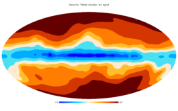
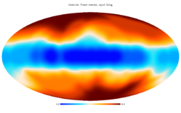
Eight Galactic emission masks are provided, giving 20, 40, 60, 70, 80, 90, 97, and 99% sky coverage, derived from the 353 GHz map after CMB subtraction. These are independent of frequency channel. Three versions are given: not apodized; and apodized by 2° and 5°. The filenames are HFI_Mask_GalPlane-apoN_2048_R2.00.fits, where N = 0, 2, and 5.
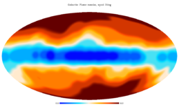
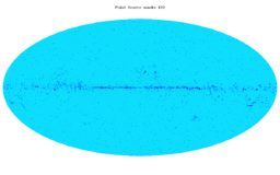
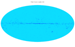
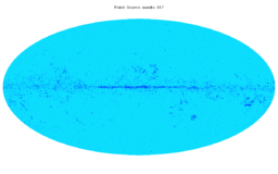
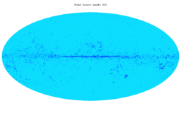
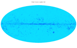
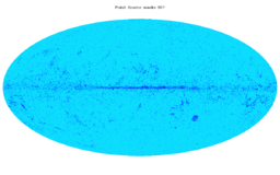
The masks are shown below. The eight "GalPlane" masks are combined (added together) and shown in a single figure for each of the three apodizations. While the result is quite clear for the case of no apodization, it is less so for the apodized case. The "PointSrc" masks are shown separately for the intensity case.
Galactic plane masks, no apodization.
Galactic plane masks, apodized to 2°.
Galactic plane masks, apodized to 5°.
Point source mask, 100 GHz.
Point source mask, 143 GHz.
Point source mask, 217 GHz.
Point source mask, 343 GHz.
Point source mask, 545 GHz.
Point source mask, 857 GHz.
File names[edit]
The FITS filenames are of the form {H|L}FI_SkyMap_fff{-tag}_Nside_R3.nn_{coverage}-{type}.fits, where "fff" are three digits to indicate the Planck frequency band, "tag" indicates the single detector or the detset (no "tag" indicates full channel), "Nside" is the HEALPix Nside value of the map, "coverage" indicates which part of the mission is covered (full, half mission, survey, year, etc.), and the optional "type" indicates the subset of input data used. The table below lists the products by type, with the appropriate unix wildcards that form the full filename.
HFI FITS filenames
| Coverage |
Filename
|
|---|
| Full channel, full mission |
HFI_SkyMap_fff{-tag}_2048_R3.??_full.fits
|
| Full channel, half mission |
HFI_SkyMap_fff{-tag}_2048_R3.??_halfmission-{1/2}.fits
|
| Full channel, full mission, odd/even ring |
HFI_SkyMap_fff{-tag}_2048_R3.??_{odd/even}ring.fits
|
LFI FITS filenames
| Coverage |
Filename |
Half-ring filename |
Comment
|
|---|
| Full channel, full mission |
LFI_SkyMap_???_1024_R3.??_full.fits |
LFI_SkyMap_???_1024_R3.??_full-ringhalf-?.fits |
70GHz is corrected for Template
|
| Full channel, full mission BandPass corrected |
LFI_SkyMap_???-BPassCorrected_1024_R3.??_full.fits |
LFI_SkyMap_???-BPassCorrected_???_1024_R3.??_full-ringhalf-?.fits |
70GHz is corrected for Template
|
| Full channel, single survey |
LFI_SkyMap_???_1024_R3.??_survey-?.fits |
n/a |
n/a
|
| Full channel, survey combination |
LFI_SkyMap_???_1024_R3.??_survey-1-3-5-6-7-8.fits |
n/a |
n/a
|
| Full channel, survey combination BandPass corrected |
LFI_SkyMap_???_1024_R3.??-BPassCorrected_survey-1-3-5-6-7-8.fits |
n/a |
n/a
|
| Full channel, single year |
LFI_SkyMap_???_1024_R3.??_year-?.fits |
n/a |
n/a
|
| Full channel, single year BandPass corrected |
LFI_SkyMap_???-BPassCorrected_1024_R3.??_year-?.fits |
n/a |
n/a
|
| Full channel, year combination |
LFI_SkyMap_???_1024_R3.??_year?-?.fits |
n/a |
n/a
|
| Full channel, year combination BandPass corrected |
LFI_SkyMap_???-BPassCorrected_1024_R3.??_year?-?.fits |
n/a |
n/a
|
| Horn pair, full mission |
LFI_SkyMap_???-??-??_1024_R3.??_full.fits |
LFI_SkyMap_???_??-??_1024_R3.??_full-ringhalf-?.fits |
n/a
|
| Single radiometer, full mission |
LFI_SkyMap_???-???_1024_R3.??_full.fits |
LFI_SkyMap_???-???_1024_R3.??_full-ringhalf-?.fits |
n/a
|
For the benefit of users who are only looking for the frequency maps with no additional information, we also provide a file combining the nine frequency maps as separate columns in a single extension. The nine columns in this file contain the intensity maps only and no other information (hits maps or variance maps) is provided.
FITS file structure[edit]
The FITS files for the sky maps contain a minimal primary header with no data, and a BINTABLE extension (EXTENSION 1, EXTNAME = FREQ-MAP) containing the data. The structure is shown schematically in the figure below. The FREQ-MAP extension contains a 3- or 10-column table that contain the signal, hit-count, and variance maps, all in HEALPix format. The 3-column case is for intensity only maps, while the 10-column case is for polarization. The number of rows is the number of map pixels, which is Npix = 12 Nside2 for HEALPix maps, where Nside = 1024 or 2048 for most the maps presented in this section.
Note that file sizes are approximately 0.6 GB for I-only maps and 1.9 GB for IQU maps at Nside=2048, but about 0.14 GB for I-only maps and 0.45 GB for IQU maps at Npix=1024 .
Keywords indicate the coordinate system ("GALACTIC"), the HEALPix ordering scheme ("NESTED"), the units (KCMB or MJy.sr-1) of each column, and of course the frequency channel ("FREQ"). Where polarization Q and U maps are provided, the "COSMO" polarization convention (used in HEALPix) is adopted, and it is specified in the "POLCCONV" keyword (see this section). The "COMMENT" fields give a one-line summary of the product, and some other information useful for traceability within the DPCs. The original filename is also given in the "FILENAME" keyword. The "BAD_DATA" keyword gives the value used by HEALPix to indicate pixels for which no signal is present (these will also have a hit-count value of 0). The main parameters are summarized in the table below.
Sky map file data structure
| 1. EXTNAME = 'FREQ-MAP' : Data columns
|
|---|
| Column name |
Data type |
Units |
Description
|
|---|
| I_STOKES |
Real*4 |
KCMB or MJy.sr-1 |
Stokes I map
|
| Q_STOKES |
Real*4 |
KCMB or MJy.sr-1 |
Stokes Q map (optional)
|
| U_STOKES |
Real*4 |
KCMB or MJy.sr-1 |
Stokes U map (optional)
|
| HITS |
Int*4 |
none |
The hit-count map
|
| II_COV |
Real*4 |
KCMB2 or (MJy.sr-1)2 |
II variance map
|
| IQ_COV |
Real*4 |
KCMB2 or (MJy.sr-1)2 |
IQ variance map (optional)
|
| IU_COV |
Real*4 |
KCMB2 or (MJy.sr-1)2 |
IQ variance map (optional)
|
| QQ_COV |
Real*4 |
KCMB2 or (MJy.sr-1)2 |
QQ variance map (optional)
|
| QU_COV |
Real*4 |
KCMB2 or (MJy.sr-1)2 |
QU variance map (optional)
|
| UU_COV |
Real*4 |
KCMB2 or (MJy.sr-1)2 |
UU variance map (optional)
|
| Keyword |
Data type |
Value |
Description
|
|---|
| PIXTYPE |
String |
HEALPIX |
|
| COORDSYS |
String |
GALACTIC |
Coordinate system
|
| ORDERING |
String |
NESTED |
Healpix ordering
|
| POLCCONV |
String |
COSMO |
Polarization convention
|
| NSIDE |
Int |
1024 or 2048 |
HEALPix Nside |
| FIRSTPIX |
Int*4 |
0 |
First pixel number
|
| LASTPIX |
Int*4 |
12 Nside2 – 1 |
Last pixel number
|
| FREQ |
String |
nnn |
Frequency channel
|
The same structure applies to all "SkyMap" products, independent of whether they are full channel, survey of half-ring. The distinction between the types of maps is present in the FITS filename (and in the traceability comment fields).
Polarization convention used in the Planck project[edit]
The FITS keyword "POLCCONV" defines the polarization convention of the data within the file.
The Planck collaboration used the COSMO convention for the polarization angle (as usually adopted in space-based and other CMB missions), whereas other subfields of astronomy usually adopt the IAU convention. The basic difference comes down to whether one thinks of the light rays being emitted from the origin (the usual mathematics/physics convention) or converging on the observer from the sky (the usual astronomy convention), and hence the "obvious" choice is different for a physicists and for an astronomer. Given that CMB results are of interest to a wide range of both physicists and astronomers, there is no single choice of convention that everyone would regard as self-evident. Hence one simply has to be aware of the convention being adopted. Because of this the Planck Collaboration has taken pains to point out which convention is being used in publications and in data releases. In the following we describe the difference between these two conventions, and the consequence if it is not taken into account correctly in the analysis.
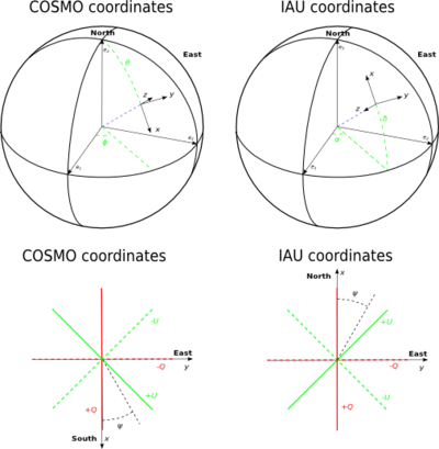
Figure 1. Polarization conventions, showing the COSMO convention (left) and IAU convention (right). The vector [math]\hat{z}[/math] points in the outward direction in COSMO, and inwards in IAU. The bottom panel refers to the plane tangent to the sphere. Changing the orientation convention is equivalent to a transformation ψ'=π-ψ of the polarization angle (Figure 1). The consequence of this transformation is the inversion of the Stokes parameter U.
The components of the polarization tensor in the helicity basis [math]\epsilon^{\pm}=(\hat{x}\pm i\hat{y})/\sqrt{2}[/math] are
[math]
(Q+iU)(\hat{n}) = \sum _{\ell m}a_{2,lm}{}_{2}Y_{\ell }^{m}(\hat{n}),
\\(Q-iU)(\hat{n}) = \sum _{\ell m}a_{-2,lm}{}_{2}Y_{\ell }^{m}(\hat{n}),
[/math]
where [math]{}_{2}Y_{\ell }^{m}(\hat{n})[/math] are the spin-weighted spherical harmonic functions.
The E and B modes can be defined as
[math]
E(\hat{n}) = \sum_{\ell m}a_{E,\ell m}Y_{\ell }^{m}(\hat{n}),
\\B(\hat{n}) = \sum_{\ell m}a_{B,\ell m}Y_{\ell }^{m}(\hat{n}),
[/math]
where the coefficients aE,ℓm and aB,ℓm are derived from linear combinations of the a2,ℓm, a-2,ℓm, defined implicitly in the first equation (Q± iU).
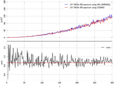
Figure 2. Error on Planck-LFI 70 GHz EE (top) and BB (bottom) power spectra, in the case of an incorrect choice being made for the polarization coordinate system convention (IAU instead of COSMO). The effect of the sign inversion of U on the polarization spectra is a non-trivial mixing of E and B modes.
An example of the typical error on EE and BB auto-spectra in the case of the wrong choice for the polarization basis is shown in Figure 2.
One should be careful to be aware of the polarization convention that is being adopted. If the IAU convention is used in computing the power spectra, then the sign of the U component of the Planck maps must be inverted before computing the E and B modes.
In astronomical applications it is common to define a pseudo-vector P to show the amplitude and orientation of
polarization on a map. When plotting these line segments to show the orientation of the plane of polarization (or the orthogonal direction, often considered to be the projection of the magnetic field), the results are the same for both the COSMO and IAU conventions. This because the appearance of P is a property of the radiation and hence not affected by the sign of U.
Note on the convention used in the Planck Catalogue of Compact Sources (PCCS)[edit]
Planck non-cosmology papers sometimes follow the IAU convention for internal analysis, for ease of comparison with other studies (e.g., comparison of Planck-derived thermal dust emission polarization with the optical polarization of starlight). Nevertheless, Planck data products, such as component-separated maps, still use the COSMO convention. The one exception is for the compact source catalogue. Because catalogues of astronomical objects found by Planck need to be compared directly with other source catalogues, the polarized sources described in the Planck Catalogue of Compact Sources follow the IAU convention, and the polarization angles are defined on an interval of [-90°,90°]. To switch to the COSMO convention, the polarization angles listed in the catalogue should be shifted by 90° and multiplied by -1.
References[edit]
- Jump up ↑ Planck intermediate results. XLVI. Reduction of large-scale systematic effects in HFI polarization maps and estimation of the reionization optical depth, Planck Collaboration Int. XLVI A&A, 596, A107, (2016).
- ↑ Jump up to: 2.02.12.22.3 Planck 2018 results. II. Low Frequency Instrument data processing, Planck Collaboration, 2020, A&A, 641, A2.
- Jump up ↑ Planck 2015 results. V. LFI calibration, Planck Collaboration, 2016, A&A, 594, A5.
- Jump up ↑ Planck 2013 results. II. Low Frequency Instrument data processing, Planck Collaboration, 2014, A&A, 571, A2.
- Jump up ↑ Planck 2015 results. II. LFI processing, Planck Collaboration, 2016, A&A, 594, A2.
- Jump up ↑ Planck 2015 results. VI. LFI mapmaking, Planck Collaboration, 2016, A&A, 594, A6.
- ↑ Jump up to: 7.07.17.27.3 Planck 2018 results. III. High Frequency Instrument data processing and frequency maps, Planck Collaboration, 2020, A&A, 641, A3.
- Jump up ↑ Planck 2013 results. VIII. HFI photometric calibration and Map-making, Planck Collaboration, 2014, A&A, 571, A8.
- ↑ Jump up to: 9.09.1
Other releases: 2020-NPIPE, 2015 and 2013[edit]
Expand
2020 - NPIPE
The NPIPE flight data maps include several subsets and differ from earlier Planck releases.
Frequency maps
All NPIPE maps, even at 545 and 857GHz, are calibrated into CMB kelvins. The temperature maps include the solar system dipole. The monopole of the maps is arbitrary. Only the seasonally-varying part of zodiacal light is removed.
Properties of the frequency maps are indicated in the following table:
| Nominal frequency [GHz] |
Eff. freq. [GHz] in T, alpha=-1a |
Eff. freq. [GHz] in P, alpha=-1b |
Eff. freq. [GHz] in T, alpha=4c |
Eff. freq. [GHz] in P, alpha=4 |
Approx. resolution [arc min]d |
Average T noise [uK-arcmin]e |
Average P noise [uK-arcmin]f |
Calibration uncertainty [%]g |
|---|
| 30 |
28.27 ± 0.03 |
same as T |
29.22 ± 0.04 |
same as T |
31.5 |
179 |
354 |
0.045
|
| 44 |
43.94 ± 0.04 |
same as T |
44.69 ± 0.03 |
same as T |
27.1 |
203 |
425 |
0.040
|
| 70 |
69.97 ± 0.04 |
same as T |
72.16 ± 0.03 |
same as T |
12.8 |
182 |
363 |
0.030
|
| 100 |
100.32 ± 0.09 |
100.31 ± 0.09 |
106.01 ± 0.06 |
106.01 ± 0.06 |
9.47 |
81.3 |
173 |
0.023
|
| 143 |
141.41 ± 0.02 |
140.75 ± 0.02 |
149.30 ± 0.01 |
148.91 ± 0.02 |
7.15 |
32.2 |
93.7 |
0.018
|
| 217 |
220.157 ± 0.005 |
219.222 ± 0.006 |
230.685 ± 0.005 |
230.060 ± 0.006 |
4.84 |
52.6 |
136 |
0.024
|
| 353 |
358.291 ± 0.005 |
357.432 ± 0.005 |
372.702 ± 0.005 |
371.774 ± 0.005 |
4.76 |
283 |
556 |
0.053
|
| 545 |
552.155 ± 0.006 |
n/a |
576.660 ± 0.004 |
n/a |
4.62 |
4680 |
n/a |
0.571
|
| 857 |
854.288 ± 0.006 |
n/a |
891.617 ± 0.006 |
n/a |
4.23 |
388000 |
n/a |
5
|
a Effective central frequency for a synchrotron-like emission. LFI uncertainties are based on a flat 30% uncertainty in each bandpass bin. HFI uncertainties use estimated statistical uncertainties in each bin.
b Polarized central frequency differs from temperature for HFI because of the non-ideal polarization sensitivity.
c Effective central frequency for a thermal dust-like emission.
d Approximate resolution is measured by fitting a Gaussian beam model to the QuickPol beam window function for intensity.
e Average noise depth is measured as the standard deviation of the simulated residual maps and includes statistical and systematic elements. Planck noise is not uniformly distributed: this value overestimates the depth near the Ecliptic poles and underestimates the depth at the Ecliptic equator. The noise is also scale-dependent, causing the depth to change in a non-trivial manner when downgrading or smoothing the maps.
f Polarized noise depth is the length of the [Q, U] error vector, not the individual Q or U uncertainty.
g Overall calibration uncertainty as reported in Table 7 of A&A 643, A42 (2020). 857GHz calibration uncertainty continues to be dominated by a 5% planetary emission model uncertainty.
All effective frequencies are based on integrals of the ground-measured detector bandpasses and noise weights as they are recorded in the accompanying instrument model. Inverse variance noise weights in each horn are symmetrized:
Half-ring maps
Half-ring frequency maps can be used to gauge instrumental noise. The large-scale systematics residuals in this split are fully correlated and cancel in the difference. The half-ring split data were destriped independently with Madam to avoid correlated noise residuals.
Single-detector maps
We provide de-polarized single-detector maps for all polarized Planck frequencies. 545 and 857GHz single-detector maps are not actively corrected for polarization modulation, but the small level of unintentional polarization sensitivity in the detectors is suppressed using the destriping templates. Single-detector maps are not corrected for bandpass mismatch. 217-857GHz single-detector maps are binned at Nside=4096 to better sample the narrow beam. 1/f noise in the detector maps is suppressed by destriping the single detector TOD with the Madam destriper code. As a result, 1/f noise residuals are not correlated between the maps. Large-scale calibration is based on full frequency data and the associated errors are correlated.
A/B split maps
Earlier Planck releases included various data splits with different degrees of correlated systematics. Any time-domain split is vulnerable to detector mismatch (beam, bandpass, etc.) that is stable over time. Full-frequency gain and bandpass-mismatch corrections used in PR3 also introduced correlated errors in the split maps that were provided. NPIPE release includes one, maximally-independent split.
For frequencies with enough redundancy, the split is based on feedhorns. Since the Planck scan strategy does not allow polarized mapmaking with fewer than two non-redundant feedhorns, the 30 and 44 GHz data could not be split by horns. Instead, these frequency channels are split in time. A half-mission split would produce incomplete sky coverage for the second half of LFI, so we use alternating years instead. Since the NPIPE A/B split is not purely time or detector set, the maps in the PLA are assigned different identifiers, as summarized below.
| Frequency [GHz] |
Subset A |
Subset B
|
|---|
| 30 |
Years 1, 3 |
Years 2, 4
|
| 44 |
Years 1, 3 |
Years 2, 4
|
| 70 |
Feedhorns 18, 20, 23 |
Feedhorns 19, 21, 22
|
| 100 |
Feedhorns 1, 4 (ds1) |
Feedhorns 2, 3 (ds2)
|
| 143 |
Feedhorns 1, 3, 5, 7 (ds3) |
Feedhorns 2, 4, 6 (ds4)
|
| 217 |
Feedhorns 1, 3, 5, 7 (ds3) |
Feedhorns 2, 4, 6, 8 (ds4)
|
| 353 |
Feedhorns 1, 3, 5, 7 (ds3) |
Feedhorns 2, 4, 6, 8 (ds4)
|
| 545 |
Feedhorn 1 (ds2) |
Feedhorns 2, 4 (ds3)
|
| 857 |
Feedhorns 1, 3 (ds3) |
Feedhorns 2, 4 (ds4)
|
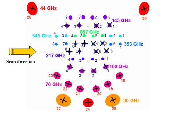
The locations of the feedhorns are indicated in the following Figure.
Physical properties of the frequency maps are indicated in the following table:
| Nominal frequency [GHz] |
Eff. freq. [GHz] in T, alpha=-1a |
Eff. freq. [GHz] in P, alpha=-1b |
Eff. freq. [GHz] in T, alpha=4c |
Eff. freq. [GHz] in P, alpha=4 |
Approx. resolution [arc min]d |
Average T noise [uK-arcmin]e |
Average P noise [uK-arcmin]f |
Calibration uncertainty [%]g |
|---|
| 30A |
28.27 ± 0.03 |
same as T |
29.22 ± 0.04 |
same as T |
31.5 |
256 |
511 |
0.064
|
| 30B |
28.27 ± 0.03 |
same as T |
29.22 ± 0.04 |
same as T |
31.5 |
255 |
510 |
0.064
|
| 44A |
43.94 ± 0.04 |
same as T |
44.69 ± 0.03 |
same as T |
27.1 |
292 |
611 |
0.057
|
| 44B |
43.94 ± 0.04 |
same as T |
44.69 ± 0.03 |
same as T |
27.1 |
290 |
610 |
0.057
|
| 70A |
70.09 ± 0.05 |
same as T |
72.23 ± 0.05 |
same as T |
13.0 |
259 |
540 |
0.043
|
| 70B |
69.86 ± 0.05 |
same as T |
72.10 ± 0.05 |
same as T |
12.7 |
256 |
545 |
0.042
|
| 100A |
100.41 ± 0.12 |
100.40 ± 0.12 |
106.16 ± 0.09 |
106.15 ± 0.09 |
9.50 |
137 |
294 |
0.039
|
| 100B |
100.27 ± 0.61 |
100.27 ± 0.61 |
105.92 ± 0.67 |
105.91 ± 0.68 |
9.44 |
97.0 |
202 |
0.027
|
| 143A |
141.65 ± 0.02 |
140.44 ± 0.02 |
149.56 ± 0.02 |
148.62 ± 0.02 |
7.17 |
42.8 |
140 |
0.024
|
| 143B |
141.14 ± 0.02 |
140.99 ± 0.02 |
149.12 ± 0.02 |
149.03 ± 0.02 |
7.13 |
48.6 |
127 |
0.027
|
| 217A |
220.248 ± 0.006 |
219.284 ± 0.008 |
230.848 ± 0.006 |
230.278 ± 0.008 |
4.83 |
73.2 |
186 |
0.033
|
| 217B |
220.064 ± 0.006 |
219.160 ± 0.008 |
230.523 ± 0.006 |
229.850 ± 0.007 |
4.84 |
76.0 |
200 |
0.035
|
| 353A |
357.571 ± 0.006 |
356.622 ± 0.007 |
371.950 ± 0.006 |
371.320 ± 0.006 |
4.75 |
322 |
751 |
0.060
|
| 353B |
359.141 ± 0.006 |
358.517 ± 0.006 |
373.572 ± 0.007 |
372.357 ± 0.006 |
4.78 |
321 |
869 |
0.060
|
| 545A |
554.398 ± 0.013 |
n/a |
579.132 ± 0.004 |
n/a |
4.75 |
5562 |
n/a |
0.679
|
| 545B |
551.162 ± 0.008 |
n/a |
575.531 ± 0.005 |
n/a |
4.56 |
4706 |
n/a |
0.574
|
| 857A |
857.886 ± 0.025 |
n/a |
894.914 ± 0.032 |
n/a |
4.22 |
394000 |
n/a |
5
|
| 857B |
850.364 ± 0.008 |
n/a |
887.862 ± 0.009 |
n/a |
4.25 |
417000 |
n/a |
5
|
a Effective central frequency for a synchrotron-like emission. LFI uncertainties are based on a flat 30% uncertainty in each bandpass bin. HFI uncertainties use estimated statistical uncertainties in each bin.
b Polarized central frequency differs from temperature for HFI because of the non-ideal polarization sensitivity.
c Effective central frequency for a thermal dust-like emission.
d Approximate resolution is measured by fitting a Gaussian beam model to the QuickPol beam window function for intensity.
e Average noise depth is measured as the standard deviation of the simulated residual maps and includes statistical and systematic elements. Planck noise is not uniformly distributed: this value overestimates the depth near the Ecliptic poles and underestimates the depth at the Ecliptic equator. The noise is also scale-dependent, causing the depth to change in a non-trivial manner when downgrading or smoothing the maps.
f Polarized noise depth is the length of the [Q, U] error vector, not the individual Q or U uncertainty.
g Overall calibration uncertainty is based on the full frequency results in Table 7 of A&A 643, A42 (2020) and scaled to the subset map noise depth. 857GHz calibration uncertainty continues to be dominated by a 5% planetary emission model uncertainty.
File names
The FITS filenames are of the form {H|L}FI_SkyMap_fff{-tag}_Nside_R4.nn_{coverage}-{type}.fits, where "fff" are three digits to indicate the Planck frequency band, "tag" indicates the single detector or the detset (no "tag" indicates full channel), "Nside" is the HEALPix Nside value of the map, "coverage" indicates which part of the mission is covered (full, half-mission, survey, year, etc.), and the optional "type" indicates the subset of input data used. The table below lists the products by type, with the appropriate unix wildcards that form the full filename.
Frequency map FITS filenames
| Coverage |
Filename
|
|---|
| Full-channel, full-mission |
?FI_SkyMap_fff{-tag}_????_R4.??_full.fits
|
| Full-channel, full-mission, half-ring |
?FI_SkyMap_fff{-tag}_????_R4.??_full-ringhalf-{1|2}.fits
|
| Subset A maps, 30 and 44GHz |
?FI_SkyMap_fff_1024_R4.??_year-1-3.fits
|
| Subset B maps, 30 and 44GHz |
?FI_SkyMap_fff_1024_R4.??_year-2-4.fits
|
| Subset A maps, 70GHz |
LFI_SkyMap_070-18-20-23_1024_R4.??_full.fits
|
| Subset B maps, 70GHz |
LFI_SkyMap_070-19-21-22_1024_R4.??_full.fits
|
| Subset A maps, 100GHz |
HFI_SkyMap_100-ds1_2048_R4.??_full.fits
|
| Subset B maps, 100GHz |
HFI_SkyMap_100-ds2_2048_R4.??_full.fits
|
| Subset A maps, 143GHz |
HFI_SkyMap_143-ds3_2048_R4.??_full.fits
|
| Subset B maps, 143GHz |
HFI_SkyMap_143-ds4_2048_R4.??_full.fits
|
| Subset A maps, 217GHz |
HFI_SkyMap_217-ds3_2048_R4.??_full.fits
|
| Subset B maps, 217GHz |
HFI_SkyMap_217-ds4_2048_R4.??_full.fits
|
| Subset A maps, 353GHz |
HFI_SkyMap_353-ds3_2048_R4.??_full.fits
|
| Subset B maps, 353GHz |
HFI_SkyMap_353-ds4_????_R4.??_full.fits
|
| Subset A maps, 545GHz |
HFI_SkyMap_545-ds2_????_R4.??_full.fits
|
| Subset B maps, 545GHz |
HFI_SkyMap_545-ds3_????_R4.??_full.fits
|
| Subset A maps, 857GHz |
HFI_SkyMap_857-ds3_????_R4.??_full.fits
|
| Subset B maps, 857GHz |
HFI_SkyMap_857-ds4_????_R4.??_full.fits
|
| Single-detector maps |
?FI_SkyMap_{detector}_????_R4.??_full.fits
|
FITS file structure
The FITS files for the sky maps contain a minimal primary header with no data, and a BINTABLE extension (EXTENSION 1, EXTNAME = FREQ-MAP) containing the data. The structure is shown schematically in the figure below. The FREQ-MAP extension contains a 3- or 10-column table that includes the signal, hit-count, and variance maps, all in HEALPix format. The 3-column case is for intensity-only maps, while the 10-column case is for polarization. The number of rows is the number of map pixels, which is Npix = 12 Nside2 for HEALPix maps, where Nside = 1024 or 2048 for most of the maps presented in this section.
Note that file sizes are approximately 0.6 GB for I-only maps and 1.9 GB for IQU maps at Nside=2048, but about 0.14 GB for I-only maps and 0.45 GB for IQU maps at Npix=1024 .
Keywords indicate the coordinate system ("GALACTIC"), the HEALPix ordering scheme ("NESTED"), the units (KCMB of each column, and of course the frequency channel ("FREQ"). Where polarization Q and U maps are provided, the "COSMO" polarization convention (used in HEALPix) is adopted, and it is specified in the "POLCCONV" keyword. The original filename is also given in the "FILENAME" keyword. The "BAD_DATA" keyword gives the value used by HEALPix to indicate pixels for which no signal is present (these will also have a hit-count value of 0). The main parameters are summarized in the table below.
Sky map file data structure
| 1. EXTNAME = 'FREQ-MAP' : Data columns
|
|---|
| Column name |
Data type |
Units |
Description
|
|---|
| I_STOKES |
Real*4 |
KCMB |
Stokes I map
|
| Q_STOKES |
Real*4 |
KCMB |
Stokes Q map (optional)
|
| U_STOKES |
Real*4 |
KCMB |
Stokes U map (optional)
|
| HITS |
Int*4 |
none |
The hit-count map
|
| II_COV |
Real*4 |
KCMB2 |
II variance map
|
| IQ_COV |
Real*4 |
KCMB2 |
IQ variance map (optional)
|
| IU_COV |
Real*4 |
KCMB2 |
IQ variance map (optional)
|
| QQ_COV |
Real*4 |
KCMB2 |
QQ variance map (optional)
|
| QU_COV |
Real*4 |
KCMB2 |
QU variance map (optional)
|
| UU_COV |
Real*4 |
KCMB2 |
UU variance map (optional)
|
| Keyword |
Data type |
Value |
Description
|
|---|
| PIXTYPE |
String |
HEALPIX |
|
| COORDSYS |
String |
GALACTIC |
Coordinate system
|
| ORDERING |
String |
NESTED |
Healpix ordering
|
| POLCCONV |
String |
COSMO |
Polarization convention
|
| NSIDE |
Int |
1024 or 2048 |
HEALPix Nside |
| FIRSTPIX |
Int*4 |
0 |
First pixel number
|
| LASTPIX |
Int*4 |
12 Nside2 – 1 |
Last pixel number
|
| FREQ |
String |
nnn |
Frequency channel
|
The same structure applies to all "SkyMap" products, independent of whether they are full channel, survey of half-ring. The distinction between the types of map is present in the FITS filename (and in the traceability comment fields).
Expand
2015 Sky temperature and polarization maps
General description
Sky maps give the best estimate of the intensity and polarization (Stokes Q and U components), if available, of the signal from the sky after removal, as far as possible, of known systematic effects (mostly instrumental, but including also the solar and earth-motion dipole, Galactic strylight and the Zodiacal light). Sky maps are provided for the full Planck mission using all valid detectors in each frequency channel, and also for various subsets by splitting the mission in various time ranges or in subsets of the detectors in a given channel. These products are useful for the study of source variability, but they are especially interesting for characterisation purposes (see also the data validation section). The details of the start and end of the time ranges are given in the table below.
To help in further processing, there are also masks of the Galactic Plane and of point sources, each provided for several different depths.
All sky maps are in Healpix format, with Nside of 1024 (LFI 30, 44 and 70) and 2048 (LFI 70 and HFI), in Galactic coordinates, and Nested ordering.
- WARNING
- the Healpix convention for polarization is NOT the same as the IAU convention - see Section 8 in this page.
The signal is given in units of Kcmb for 30-353 GHz, and of MJy/sr (for a constant [math]\nu F_\nu[/math] energy distribution ) for 545 and 857 GHz. For each frequency channel, the intensity and polarization maps are packaged into a BINTABLE extension of a FITS file together with a hit-count map (or hit map, for short, giving the number of observation samples that are cumulated in a pixel, all detectors combined) and with the variance and covariance maps. Additional information is given in the FITS file header. The structure of the FITS file is given in the FITS file structure section below.
- R2.00
- this first release (Jan 2015) contains polarisation data for the 353 GHz channel only.
- R2.01
- this second release (May 2015) adds polarisation data to the 100-217 GHz channels.
- R2.02
- a full re-release to correct the Healpix bad pixel value in the maps which was altered during the preparation of the maps and not reset to the correct value (the valid pixels are unchanged). It also fixes some FITS keywords, and includes a full re-release of the Zodi correction maps, with the 100-217 GHz one now including the polarisation correction)
Ranges for mission and surveys
| Range |
ODs |
HFI rings |
pointing-IDs |
Comment
|
|---|
| nominal mission |
91 - 563 |
240 - 14723 |
00004200 - 03180200 |
|
| full mission |
91 - 974 |
240 - 27005 |
00004200 - 05322620 |
for HFI
|
| full mission |
91 - 1543 |
n/a |
00004200 - 06511160 |
for LFI
|
| Survey 1 |
91 - 270 |
240 - 5720 |
00004200 - 01059820 |
|
| Survey 2 |
270 - 456 |
5721 - 11194 |
01059830 - 02114520 |
|
| Survey 3 |
456 - 636 |
11195 - 16691 |
02114530 - 03193660 |
|
| Survey 4 |
636 - 807 |
16692 - 21720 |
03193670 - 04243900 |
|
| Survey 5 |
807 - 974 |
21721 - 27005 |
05267180 - 05322590 |
end of mission for HFI
|
| Survey 5 |
807 - 993 |
n/a |
05267180 - 06344800 |
end of survey for LFI
|
| Survey 6 |
993 - 1177 |
n/a |
06344810 - 06398120 |
LFI only
|
| Survey 7 |
1177 - 1358 |
n/a |
06398130 - 06456410 |
LFI only
|
| Survey 8 |
1358 - 1543 |
n/a |
06456420 - 06511160 |
LFI only
|
| Survey 9 |
1543 - 1604 |
n/a |
06511170 - 06533320 |
LFI only Not in this delivery
|
| HFI mission-half-1 |
91 - 531 |
240 - 13471 |
00004200 - 03155580 |
|
| HFI mission-half-2 |
531 - 974 |
13472 - 27005 |
03155590 - 05322590 |
|
| LFI Year 1 |
91 - 456 |
n/a |
00004200 - 02114520 |
|
| LFI Year 2 |
456 - 807 |
n/a |
02114530 - 04243900 |
|
| LFI Year 3 |
807 - 1177 |
n/a |
05267180 - 06398120 |
|
| LFI Year 4 |
1177 - 1543 |
n/a |
06398130 - 06511160 |
|
Production process
Sky maps are produced by combining appropriately the data of all working detectors in a frequency channel over some period of the mission. They give the best estimate of the signal from the sky (unpolarised) after removal, as far as possible, of known systematic effects and of the dipole signals induced by the motion of the solar system in the CMB and of the Planck satellite in the solar system. In particular, they include the Zodiacal light emission (Zodi for short) and also the scattering from the far-side lobes of the beams (FSL). More on this below.
HFI processing
The mapmaking and calibration process is described in detail in the Map-making section and in the Planck-2015-A08[1] paper, where detailed references are found. In brief it consists of:
- binning the TOI data onto rings
- Healpix rings (HPRs) are used here, each ring containing the combined data of one pointing period.
- flux calibration
- at 100-353 GHz, the flux calibration factors are determined by correlating the signal with the orbital dipole, which is determined very accurately from the Planck satellite orbital parameters provided by Flight Dynamics. This provides a single gain factor per bolometer. At 545 and 857 GHz the gain is determined from the observation of Uranus and Neptune (but not Jupiter which is too bright) and comparison to recent models made explicitly for this mission. A single gain is applied to all rings at these frequencies.
- destriping
- in order to remove low-frequency noise, an offset per ring is determined by minimizing the differences between HPRs at their crossings, and removed.
- Zodiacal light correction
- a Zodiacal light model is used to build HPRs of the the Zodi emission, which is subtracted from the calibrated HPRs.
- projection onto the map
- the offset-corrected, flux-calibrated, and Zodi-cleaned HPRs are projected onto Healpix maps, with the data of each bolometer weighted by a factor of 1/NET of that bolometer.
These steps are followed by some post-processing which is designed to prepare the maps for the component separation work. This post processing consists of:
- Dust bandpass leakage correction
- the Q and U maps are corrected for the intensity-to-polarisation leakage caused by the foregrounds having a non-CMB spectrum, and as a consequence of the non-identical bandpasses on the different detectors (bandpass mismatch, or BPM). This correction is determined using the ground method as described in Section 7.3 of Planck-2015-A08[1]. These correction maps can be found in the Planck Legacy Archive as HFI_CorrMap_???-dustleak-ground_2048_R2.0?_{coverage}.fits. The correction is applied by subtracting the correction map from the corresponding input map. This correction is not applied to the nominal mission maps in order to maintain compatibility with the PR1 products. In fact this correction was computed and applied only to the products used in component separation, so they were not applied to the single survey maps and to the half-ring maps, which are considered characterisation products.
- Far Side Lobe calibration correction
- the 100-217 maps are multiplied by factors of 1.00087, 1.00046, and 1.00043, respectively, to compensate for the non-removal of the far-side lobes, and similarly the corresponding covariance maps have also been corrected by multiplication by the square of the factor.
- Fill missing pixels
- missing pixels are filled in with a value that is the mean of valid pixels within a given radius. A radius of 1 deg is used for the full channel maps, and 1.5 deg is used for the detset maps. This step is not applied to the single survey maps since they have large swaths of the sky that are not covered.
- Map zero-level
- for the 100 to 857 GHz maps, the zero levels are set to their optimal levels for Galactic and CIB studies. A procedure for adjusting them to astrophysical values is given in the HFI Mapmaking and Calibration paper Planck-2015-A08[1].
These maps provide the main mission products. Together with signal maps, hit count, variance, and variance maps are also produced. The hit maps give the (integer) number of valid TOI-level samples that contribute to the signal of each pixel. All valid samples are counted in the same way, i.e., there is no weighting factor applied. The variance maps project the white noise estimate, provided by the NETs, in the sky domain.
Note that the nominal mission maps have not had the post-processing applied, which makes them more easily comparable to the PR1 products.
LFI processing
LFI maps were constructed with the Madam map-making code, version 3.7.4. The code is based on generalized destriping technique, where the correlated noise component is modeled as a sequence of constant offset, called baselines. A noise filter was used to constrain the baseline solution allowing the use of 0.25 s and 1 second baselines for the 30 and 44, 70 GHz respectively.
Radiometers were combined according to the horn-uniform weighting scheme to minimize systematics. The used weights are listed in Map-making. The flagged samples were excluded from the analysis by setting their weights to [math]C_{w}^{-1}[/math] = 0. The galaxy region was masked out in the destriping phase, to reduce error arising from strong signal gradients. The polarization component was included in the analysis...
- Dipole and Far Side Lobe correction
- input timelines are cleaned by 4pi convolved dipole and Galactic Straylight obtained as convolution of the 4pi in band far sidelobes and Galactic Simulation as explained in Section 7.4 of Planck-2015-A02[2].
Beam effects on the LFI maps are described in Section 7.1 of Planck-2015-A02[2]. Scaling of the maps due to beam effects is taken into account in the LFI's beam functions (as provided in the RIMO, give reference) which should be used for analysis of diffuse components. To compute the flux densities of compact sources, correction must be made for beam effects (see Table 8 of Planck-2015-A02[2])."
- Bandpass leakage correction
- as opposed to the HFI, the LFI high resolution maps have not been corrected for bandpass leakage. Only low resolution (nside 256) maps are provided with the bandpass correction. The correction maps (LFI_CorrMap_0??-BPassCorr_*.fits) can be found in the Planck Legacy Archive. Further details about the procedure used to generate the bandpass correction maps can be found in Section 11 of Planck-2015-A02[2].
- Map zero-level
- for the 30, 44 and 70 GHz, maps are corrected for zero level monopole by applying an offset correction, see LFI Calibration paper Planck-2015-A05[3]. Note that the offset applied is indicated in the header as a comment keyword.
A detailed description of the map-making procedure is given in Planck-2013-II[4], Planck-2015-A02[2], Planck-2015-A06[5] and in section Map-making.
Types of maps
Full mission, full channel maps (6 HFI, 4 LFI)
Full channel maps are built using all the valid detectors of a frequency channel and cover the either the full or the nominal mission. For HFI, the 143-8 and 545-3 bolometers are rejected entirely as they are seriously affected by RTS noise. HFI provides the Q and U components for the 100, 143, 217 and 353 GHz channels only. LFI provides the I, Q and U maps for all the channels. Reminder: HFI Q and U maps are corrected for bandpass leakage but LFI Q and U maps are not. The I, Q and U maps are displayed in the figures below. The color range is set using a histogram equalisation scheme (from HEALPIX) that is useful for these non-Gaussian data fields. For visualization purposes, the Q and U maps shown here have been smoothed with a 1 degree Gaussian kernel, otherwise they look like noise to the naked eye.
The 70 GHz full map is available also at [math]N_{side}[/math] 2048.
Full mission light maps, full channel maps (6 HFI, 7 LFI)
These maps are based on the Full mission maps but contain fewer columns, IQU from 30 to 353 GHz, and I only at 545 and 857 GHz. These maps have been produced to reduce the transfer time of the most downloaded frequency full mission maps.
Nominal mission, full channel maps (6 HFI)
These maps are similar to the ones above, but cover the nominal mission only. They are meant primarily to be compared to the PR1 products in order to see the level of improvements in the processing. Because of this, they are produced in Temperature only, and have not had the post-processing applied.
Single survey, full channel maps (30 HFI, 35 LFI)
Single survey maps are built using all valid detectors of a frequency channel; they cover separately the different sky surveys. The surveys are defined as the times over which the satellite spin axis rotates but 180 degrees, which, due to the position of the detectors in the focal plane does not cover the full sky, but a fraction between ~80 and 90% depending on detector position. During adjacent surveys the sky is scanned in opposite directions. More precisely it is the ecliptic equator that is scanned in opposite directions. While these are useful to investigate variable sources, they are also used to study the systematics of the time-response of the detectors as they scan bright sources, like the Galactic Plane, in different directions during different survey. Note that the HFI and LFI missions cover 5 and 8 surveys, respectively, and in case of HFI the last survey in incomplete.
The 70 GHz surveys maps are available also at [math]N_{side}[/math] 2048.
Note LFI provide a special surveys maps combination used in the low l analysis. This maps, available at the three LFI frequency 30, 44 and 70 GHz, was built using the combination of survey 1, 3, 5, 6, 7 and 8.
Year maps, full channel maps (12 HFI, 16 LFI)
These maps are built using the data of surveys 1+2, surveys 3+4, and so forth. They are used to study long-term systematic effects.
The 70 GHz years maps are available also at [math]N_{side}[/math] 2048.
Half-mission maps, full channel maps (12 HFI, 12 LFI)
For HFI, the half mission is defined after eliminating those rings discarded for all bolometers. There are 347 such rings, may of which are during the 5th survey when the End-of-Life tests were performed. The remaining 26419 rings are divided in half (up to the odd ring) to define the two halves of the mission. This exercise is done for the full mission only.
For LFI instead of the half-mission the following year combination has been created: Year 1+2, Year 1+3, Year 2+4, Year 3+4,
Full mission, single detector maps (18 HFI, 22 LFI)
IN case of HFI these maps are built only for the SWBs (non polarized) and contain only temperature data, of course. They are not built for the polarisation sensitive detectors because they are not fixed on the sky as the polarisation component depends on the position angle at the time of observation. Instead, we provide maps built by quads of polarisation-sensitive detectors (see next section), which have different polarisation angles and that can be used to built I, Q, and U maps
HFI Temperature sensitive bolometers
| Frequency |
Detector names
|
|---|
| 143 GHz |
143-5, 6, 7
|
| 217 GHz |
217-1, 2, 3, 4
|
| 353 GHz |
353-1, 2, 7, 8
|
| 545 GHz |
545-1, 2, 4
|
| 857 GHz |
857-1, 2 , 3, 4
|
The 143-8 and 353-3 bolometer data are affected by strong RTS (random telegraphic signal) noise. They have not been used in the data processing, and are not delivered. For a figure showing the focal plane layout, see this Introduction of the Detector Pointing chapter.
In case of LFI, all the 22 Radiometers maps are available, those, obviously, are only in temperature.
Full mission, detector set or detector pairs maps (8 HFI, 8 LFI)
The objective here is to build independent temperature (I) and polarisation (Q and U) maps with the two pairs of polarisation sensitive detectors of each channel where they are available, i.e. in the 44-353 GHz channels. The table below indicates which detectors were used to built each detector set (detset).
Definition of HFI Detector Sets
| Frequency |
DetSet1 |
DetSet2
|
|---|
| 100 GHz |
100-1a/b & 100-4a/b |
100-2a/b & 100-3a/b
|
| 143 GHz |
143-1a/b 1 & 43-3a/b |
143-2a/b & 143-4a/b
|
| 217 GHz |
217-5a/b & 217-7a/b |
217-6a/b & 217-8a/b
|
| 353 GHz |
353-3a/b & 353-5a/b |
353-4a/b & 353-6a/b
|
Definition of LFI Detector Pairs
| Frequency |
Horn Pair |
Comment
|
|---|
| 44 GHz |
24 |
This maps is only in temperature
|
| 44 GHz |
25 & 26 |
|
| 70 GHz |
18 & 23 |
Available also at [math]N_{side}[/math] = 2048
|
| 70 GHz |
19 & 22 |
Available also at [math]N_{side}[/math] = 2048
|
| 70 GHz |
20 & 21 |
Available also at [math]N_{side}[/math] = 2048
|
Half-ring maps (64 HFI, 62 LFI)
These maps are similar to the ones above, but are built using only the first or the second half of each ring (or pointing period). The HFI provides half-ring maps for the full mission only, and for the full channel, the detsets, and the single bolometers. The LFI provides half-rings maps for the channel full mission (70 GHz also at [math]N_{side}[/math] 2048), for the radiometer full mission and the horn pairs full mission.
The Zodiacal light correction maps
The Zodiacal light signal depends on the location of the observer relative to the Zodiacal light bands, and thus it is not a fixed pattern on the sky but depends on the period of observation. The maps presented here are the difference between the uncorrected (and not delivered) and the corrected maps.
Note that while the Zodiacal light model that is subtracted at ring level (see here) is not polarised, the corrections are not null and Q and U. This is suspected to come from some combination of leakage due to bandpass differences and beam mismatch, and maybe other effects. These leakages are typically of order a few %, at max, of the maximum zodi intensity at I for each channel. They range from ~150 nK at 100 GHz to ~5 uK at 353 GHz.
Caveats and known issues
- HFI polarization 100-217 GHz
- at low multipoles, despite the progress that has been made to control the systematic effects present in the maps, polarization data between 100-217 GHz are still contaminated by systematic residuals. Figure 10 of Planck-2015-A08[1] shows the EE power spectra from the half-difference maps at 100, 143, and 217 GHz and compared to the noise power spectrum from FFP8 simulations. he half-ring differences are compatible with noise while, at multipoles typically lower than 50, detector-set and half-mission differences are dominated by excess power which is larger than the EE CMB signal. The Planck Collaboration has used the range ell>30 to carry out component separation (Planck-2015-A09[6]), as data at ell<30 is not considered usable for cosmological analyses. The origin of the excess power will be explored in a forthcoming publication.
Inputs
HFI inputs
The HFI mapmaking takes as input:
- the cleaned TOIs of signal of each detector, together with their flags, produced by the TOI processing pipeline;
- the TOIs of pointing (quaternions), described in Detector pointing;
- bolometer-level characterization data, from the DPC's internal IMO (not distributed);
- Planck orbit data, used to compute and remove the Earth's dipole;
- Planck solar dipole information, used to calibrate the CMB channels;
- Planet models used to calibrate the Galactic channels.
LFI inputs
The Madam mapmaker takes as input:
- the calibrated timelines (for details see TOI Processing);
- the detector pointings (for details see Detector pointing);
- the noise information in the form of 3-parameter (white noise level, σ, slope, and knee frequency, fknee) noise model (for details see RIMO)
Related products
Masks
This section presents the masks of the point sources and of the Galactic plane. These are general purpose masks. Other masks specific to certain products are packaged with the products.
Point source masks
For HFI and LFI two sets of masks are provided:
- Intensity masks, which removes sources detected with SNR > 5.
- Polarisation masks, which remove sources which have polarisation detection significance of 99.97 % or greater at the position of a source detected in intensity. They were derived from the polarisation maps with dust ground bandpass mismatch leakage correction applied. The cut around each source has a radius of 3σ (width) of the beam ~ 1.27 FWHM (for LFI the cut around each source has a radius of 32 arcmin at 30GHz, 27 arcmin at 44 GHz and 13 arcmin at 70 GHz).
Both sets are found in the files HFI_Mask_PointSrc_2048_R2.00.fits and LFI_Mask_PointSrc_2048_R2.00.fits in which the first extension contains the Intensity masks, and the second contains the Polarisation masks.
Galactic plane masks
Eight masks are provided giving 20, 40, 60, 70, 80, 90, 97, and 99% sky coverage derived from the 353 GHz map, after CMB subtraction. They are independent of frequency channel. Three versions of these are given: not apodized, and apodized by 2 and 5 deg. The filenames are HFI_Mask_GalPlane-apoN_2048_R2.00.fits, where N = 0, 2, 5.
The masks are shows below. The 8 GalPlane masks are combined (added together) and shown in a single figure for each of the three apodization. While the result is quite clear for the case of no apodization, it is less so for the apodized case. The point source masks are shown separately for the Intensity case.
Galactic Plane masks, no apod
Galactic Plane masks, apod 2 deg
Galactic Plane masks, apod 5 deg
File names
The FITS filenames are of the form {H|L}FI_SkyMap_fff{-tag}_Nside_R2.nn_{coverage}-{type}.fits, where fff are three digits to indicate the Planck frequency band, tag indicates the single detector or the detset, Nside is the Healpix Nside of the map, coverage indicates which part of the mission is covered (full, half mission, survey, year, ...) , and the optional type indicates the subset of input data used. The table below lists the products by type, with the appropriate unix wildcards that form the full filename.
HFI FITS filenames
| Coverage |
filename |
half-ring filename
|
|---|
| Full chan, full mission |
HFI_SkyMap_???_2048_R2.??_full.fits |
HFI_SkyMap_???_2048_R2.??_full-ringhalf-?.fits
|
| Full channel, nominal mission |
HFI_SkyMap_???_2048_R2.??_nominal.fits |
n/a
|
| Full channel, single survey |
HFI_SkyMap_???_2048_R2.??_survey-?.fits |
n/a
|
| Full channel, single year |
HFI_SkyMap_???_2048_R2.??_year-?.fits |
n/a
|
| Full channel, half mission |
HFI_SkyMap_???_2048_R2.??_halfmission*-?.fits |
n/a
|
| Det-set, full mission |
HFI_SkyMap_???-ds?_2048_R2.??_full.fits |
HFI_SkyMap_???-ds?_2048_R2.??_full-ringhalf-?.fits
|
| Single SWB, full mission |
HFI_SkyMap_???-?_2048_R2.??_full.fits |
HFI_SkyMap_???-?_2048_R2.??_full-ringhalf-?.fits
|
LFI FITS filenames
| Coverage |
filename |
half-ring filename |
Comment
|
|---|
| Full channel, full mission |
LFI_SkyMap_???_1024_R2.??_full.fits |
LFI_SkyMap_???_1024_R2.??_full-ringhalf-?.fits |
Available also at Nside = 2048
|
| Full channel, single survey |
LFI_SkyMap_???_1024_R2.??_survey-?.fits |
n/a |
Available also at Nside = 2048
|
| Full channel, survey combination |
LFI_SkyMap_???_1024_R2.??_survey-1-3-5-6-7-8.fits |
n/a |
n/a
|
| Full channel, single year |
LFI_SkyMap_???_1024_R2.??_year-?.fits |
n/a |
Available also at Nside = 2048
|
| Full channel, year combination |
LFI_SkyMap_???_1024_R2.??_year?-?.fits |
n/a |
n/a
|
| Horn pair, full mission |
LFI_SkyMap_???-??-??_1024_R2.??_full.fits |
LFI_SkyMap_???_??-??_1024_R2.??_full-ringhalf-?.fits |
Available also at Nside = 2048
|
| Single radiometer, full mission |
LFI_SkyMap_???-???_1024_R2.??_full.fits |
LFI_SkyMap_???-???_1024_R2.??_full-ringhalf-?.fits |
n/a
|
For the benefit of users who are only looking for the frequency maps with no additional information, we also provide a file combining the 9 frequency maps as separate columns in a single extension. The 9 columns in this file contain the intensity maps ONLY and no other information (hit maps and variance maps) is provided.
FITS file structure
The FITS files for the sky maps contain a minimal primary header with no data, and a BINTABLE extension (EXTENSION 1, EXTNAME = FREQ-MAP) containing the data. The structure is shows schematically in the figure below. The FREQ-MAP extension contains a 3- or a 10-column table that contain the signal, hit-count and variance maps, all in Healpix format. The 3-column case is for intensity only maps, the 10-column case is for polarisation. The number of rows is the number of map pixels, which is Npix = 12 [math]N_{side}[/math]2 for Healpix maps, where [math]N_{side}[/math] = 1024 or 2048 for most the maps presented in this chapter.
Note that file sizes are ~0.6 GB for I-only maps and ~1.9 GB for I,Q,U maps at [math]N_{side}[/math] 2048 and ~0.14 GB for I-only maps and ~0.45 GB for I,Q,U maps at [math]N_{side}[/math] 1024 .
Keywords indicate the coordinate system (GALACTIC), the Healpix ordering scheme (NESTED), the units (K_cmb or MJy/sr) of each column, and of course the frequency channel (FREQ). Where polarisation Q and U maps are provided, the COSMO polarisation convention (used in HEALPIX) is adopted, and it is specified in the POLCCONV keyword (see this section. The COMMENT fields give a one-line summary of the product, and some other information useful for traceability within the DPCs. The original filename is also given in the FILENAME keyword. The BAD_DATA keyword gives the value used by Healpix to indicate pixels for which no signal is present (these will also have a hit-count value of 0). The main parameters are summarised below:
Sky map file data structure
| 1. EXTNAME = 'FREQ-MAP' : Data columns
|
|---|
| Column Name |
Data Type |
Units |
Description
|
|---|
| I_STOKES |
Real*4 |
K_cmb or MJy/sr |
The Stokes I map
|
| Q_STOKES |
Real*4 |
K_cmb or MJy/sr |
The Stokes Q map (optional)
|
| U_STOKES |
Real*4 |
K_cmb or MJy/sr |
The Stokes U map (optional)
|
| HITS |
Int*4 |
none |
The hit-count map
|
| II_COV |
Real*4 |
K_cmb2 or (MJy/sr)2 |
The II variance map
|
| IQ_COV |
Real*4 |
K_cmb2 or (MJy/sr)2 |
The IQ variance map (optional)
|
| IU_COV |
Real*4 |
K_cmb2 or (MJy/sr)2 |
The IQ variance map (optional)
|
| QQ_COV |
Real*4 |
K_cmb2 or (MJy/sr)2 |
The QQ variance map (optional)
|
| QU_COV |
Real*4 |
K_cmb2 or (MJy/sr)2 |
The QU variance map (optional)
|
| UU_COV |
Real*4 |
K_cmb2 or (MJy/sr)2 |
The UU variance map (optional)
|
| Keyword |
Data Type |
Value |
Description
|
|---|
| PIXTYPE |
string |
HEALPIX |
|
| COORDSYS |
string |
GALACTIC |
Coordinate system
|
| ORDERING |
string |
NESTED |
Healpix ordering
|
| POLCCONV |
String |
COSMO |
Polarization convention
|
| NSIDE |
Int |
1024 or 2048 |
Healpix [math]N_{side}[/math]
|
| FIRSTPIX |
Int*4 |
0 |
First pixel number
|
| LASTPIX |
Int*4 |
12 [math]N_{side}[/math]2 – 1 |
Last pixel number
|
| FREQ |
string |
nnn |
The frequency channel
|
The same structure applies to all SkyMap products, independent of whether they are full channel, survey of half-ring. The distinction between the types of maps is present in the FITS filename (and in the traceability comment fields).
Polarization convention used in the Planck project
The Planck collaboration used the COSMO convention for the polarization angle (as usually used in space based CMB missions), whereas other astronomical fields usually use the IAU convention. In the following document we report the difference between these two conventions, and the consequence if it is NOT taken into account correctly in the analysis.
Figure 1. COSMO convention (left) and IAU convention (right). The versor [math]\hat{z}[/math] points outwards the pointing direction in COSMO, and inwards in IAU. The bottom panel refers to the plane tangent to the sphere. Changing the orientation convention is equivalent to a transformation [math]\psi'=\pi-\psi[/math] of the polarization angle (Figure 1). The consequence of this transformation is the inversion of the Stokes parameter [math]U[/math].
The components of the polarization tensor in the helicity basis [math]\epsilon^{\pm}=1/\sqrt{2}(\hat{x}\pm i\hat{y})[/math] are:
[math]
(Q+iU)(\hat{n}) = \sum _{\ell m}a_{2,lm}{}_{2}Y_{\ell }^{m}(\hat{n})
\\(Q-iU)(\hat{n}) = \sum _{\ell m}a_{-2,lm}{}_{2}Y_{\ell }^{m}(\hat{n})
[/math]
where [math]{}_{2}Y_{\ell }^{m}(\hat{n})[/math] are the spin weighted spherical harmonic functions.
The [math]E[/math] and [math]B[/math] modes can be defined as:
[math]
E(\hat{n}) = \sum_{\ell m}a_{E,\ell m}Y_{\ell }^{m}(\hat{n})
\\B(\hat{n}) = \sum_{\ell m}a_{B,\ell m}Y_{\ell }^{m}(\hat{n})
[/math]
where the coefficients [math]a_{E,\ell m}[/math] and [math]a_{B,\ell m}[/math] are derived from linear combinations of the [math]a_{2,\ell m}[/math] , [math]a_{-2,\ell m}[/math] defined implicitly in the first equation ([math]Q\pm iU[/math]).
Figure 2. Error on Planck-LFI 70 GHz [math]EE[/math] (top) and [math]BB[/math] (bottom) spectra, in case of wrong choice of the coordinate system convention (IAU instead of COSMO). The effect of the sign inversion of [math]U[/math] on the polarization spectra is a non trivial mixing of [math]E[/math] and [math]B[/math] modes.
An example of the typical error on [math]EE[/math] and [math]BB[/math] auto-spectra in case of a wrong choice of the polarization basis is shown in Figure 2.
BE CAREFUL about the polarization convention you are using. If the IAU convention is used in computing the power spectra, the sign of the [math]U[/math] component of the Planck maps must be inverted before computing [math]E[/math] and [math]B[/math] modes.
Note on the convention used by the Planck Catalogue of Compact Sources (PCCS)
For continuity with other compact sources catolgues, the Catalogue of Compact Sources provided by Planck follows the IAU convention, and the polarization angles are defined on an interval of [-90°,90°]. To switch to the COSMO convention, the polarization angles listed in the catalogue have to be shifted by 90° and multiplied by -1.
References[edit]
- ↑ Jump up to: 1.01.11.21.3 Planck 2015 results. VIII. High Frequency Instrument data processing: Calibration and maps, Planck Collaboration, 2016, A&A, 594, A8.
- ↑ Jump up to: 2.02.12.22.32.4 Planck 2015 results. II. LFI processing, Planck Collaboration, 2016, A&A, 594, A2.
- Jump up ↑ Planck 2015 results. V. LFI calibration, Planck Collaboration, 2016, A&A, 594, A5.
- Jump up ↑ Planck 2013 results. II. Low Frequency Instrument data processing, Planck Collaboration, 2014, A&A, 571, A2.
- Jump up ↑ Planck 2015 results. VI. LFI mapmaking, Planck Collaboration, 2016, A&A, 594, A6.
- Jump up ↑ Planck 2015 results. XI. Diffuse component separation: CMB maps, Planck Collaboration, 2016, A&A, 594, A9.
Expand
2013 Sky temperature maps
General description
Sky maps give the best estimate of the intensity of the signal from the sky after removal, as far as possible, of known systematic effects and of the dipole signals induced by the motion of the solar system in the CMB and of the Planck satellite in the solar system. Sky maps are provided for the nominal Planck mission and also, separately, for the first two single surveys, the third one being covered only for a small part during the nominal mission.The details of the start and end times of each are given in this table. As a secondary product, maps with estimates of the Zodiacal light and Far-Side-Lobes contribution removed are also provided.
For characterization purposes, are also provided maps covering the nominal survey but each one using only half of the available data. These are the ringhalf_{1|2} maps, which are built using the first and second half of the stable pointing part in each pointing period. These maps are used extensively to investigate the (high frequency) noise properties the maps themselves and of other products described elsewhere (see e.g., the data validation section).
To help in further processing, there are also masks of the Galactic Plane and of point sources, each provided for several different depths.
All sky maps are in Healpix format, with Nside of 2048 for HFI and of 1024 for LFI (note that the LFI 70 GHz has been delivered also at Nside of 2048 to be directly comparable with HFI maps), in Galactic coordinates, and Nested ordering. The signal is given in units of Kcmb for 30-353 GHz, and of MJy/sr (for a constant $\nu F_\nu$ energy distribution ) for 545 and 857 GHz. Each sky map is packaged into a BINTABLE extension of a FITS file together with a hit-count map (or hit map, for short, giving the number of observation samples that are cumulated in a pixel, all detectors combined) and a variance map (determined from the half-ring maps), and additional information is given in the FITS file header. The structure of the FITS file is given in the FITS file structure section below.
Types of maps
- Full channel maps
- Full channel maps are built using all the valid detectors of a frequency channel and cover the nominal mission. For HFI, the 143-8 and 545-3 bolometers are rejected entirely as they are seriously affected by RTS noise. The maps are displayed in the figures below. The range is the same from 30 - 143 GHz in order to show the CMB at the same level. At higher frequencies the range is increased in order to keep the Galactic Plane from invading the whole sky.
- Single survey maps
- Single survey maps are built using all valid detectors of a frequency channel; they cover separately the different sky surveys. The surveys are defined as the times over which the satellite spin axis rotates but 180 degrees, which, due to the position of the detectors in the focal plane does not cover the full sky, but a fraction between ~80 and 90% depending on detector position.
- Detector set or detector pairs maps
- These are maps built from a subset of the detectors in a frequency channel, typically our of two PSB pairs (i.e., four poloarisation-sensitive bolometers with different orientation on the sky), for HFI in order to extract a single temperature map. While none of these maps are part of the first Planck data release, the concept of detset is used, and thus it is worth mentioning it here. In particular, information by detector set is available at the sky power spectrum level and in the RIMO.
- Half-ring maps
- Half-ring maps are built using only the first or the second half of the stable pointing period data. There are thus two half-ring maps per frequency channel named ringhalf_1 and ringhalf_2 respectively. These maps are built for characterization purposes in order to perform null tests. In particular, the difference between the two half-ring maps at a given frequency give a good estimate of the high frequency noise in the data (albeit biased low by ~0.5% for the HFI channels due to specifics of the TOI processing).
- Masks
- Masks are provided of the Galactic Plane and of the point sources. For the Galactic Plane, eight masks are given covering different fractions of the sky, and for the points sources two masks are given, at the 5 and 10 sigma level, for each Planck HFI frequency channel. These are generic masks, specific masks applicable to other products are delivered with the products themselves.
Caveats and known issues
The primary limitation of the HFI maps are
- the absence of correction of the ADC non-linearities,
- the far-side lobe contribution is not accounted for in the processing and in the calibration,
- the dipole removal is based on the non-relativistic approximation which leaves a weak quadrupole component in the map.
And thus the overall calibration accuracy is at the 0.2% level in 100-217 GHz channels
The LFI 70 GHz maps at Nside=2048 should be considered as additional product, the default are the LFI maps at Nside=1024. No effective beam at Nside=2048 is provided, only at Nside=1024, for this reason the use of the effective beam with maps at Nside 2048 is discouraged.
Map zero-level
For the 100 to 857 GHz maps, the zero levels are set to their optimal levels for Galactic and CIB studies. A procedure for adjusting them to astrophysical values is given in the HFI Calibration paper Planck-2013-VIII[1].
For the 30, 44 and 70 GHz, maps are corrected for zero level monopole by applying an offset correction, see LFI Calibration paper Planck-2013-V[2] section 3.4 "Setting the zero levels in the maps". Note that the offset applied is indicated in the header as a comment keyword.
The Zodiacal light and the Far-Side Lobes
The figures below show the modeled Zodiacal light and Far Side Lobes projected onto the maps; they are simply the difference between the main product and the ZodiCorrected maps for the nominal mission. The units are given in the figures. The heat color table has been used in place of the standard Planck for clarity reasons.
zodi/FSL rediduals - 100 GHz
zodi/FSL rediduals - 143 GHz
zodi/FSL rediduals - 217 GHz
zodi/FSL rediduals - 353 GHz
zodi/FSL rediduals - 545 GHz
zodi/FSL rediduals - 857 GHz
The effects of the FSLs are seen most clearly at the highest frequencies, as structures roughly symmetric about the center of the image, which corresponds to the location of the Galactic Centre, which is in turn the source of most of the radiation that is scattered into the FSLs.
Artifacts near caustics of the scanning strategy
The scanning strategy is such that regions around the Ecliptic poles are surveyed very deeply and compared to the average, and the transition from the nominal depth to the high depth, as shows on hit-count maps is very rapid, namely a few pixels, for a contrast of ~30. These transitions, or caustics in the maps, occur at different positions on the sky for different detectors, as the positions depend on their location in the focal plane of the instrument. As a result, when data from different detectors are combined to build a full channel map, the the weights of different detectors in the mix changes rapidly across the caustic, and given the remaining errors in the relative calibration of the detectors, a visible effect can be introduced in the maps, especially when the SNR is very high, i.e. at the highest frequencies and near bright regions like the Galactic Plane. Some examples are shown below.
857 GHz intensity map around (272.5, -27)
857 GHz intensity map around (264.5, -37.5)
857 GHz intensity map around (98.5, 43)
857 GHz hit count map around (272.5, -27)
857 GHz hit count map around (264.5, -37.5)
857 GHz hit count map around (98.5, 43)
Production process
Sky maps are produced by combining appropriately the data of all working detectors in a frequency channel over some period of the mission. They give the best estimate of the signal from the sky (unpolarised) after removal, as far as possible, of known systematic effects and of the dipole signals induced by the motion of the solar system in the CMB and of the Planck satellite in the solar system. In particular, they include the Zodiacal light emission (Zodi for short) and also the scattering from the far-side lobes of the beams (FSL). More on this below.
HFI processing
The inputs to the mapmaking are TOIs of signal that have been cleaned (as far as possible) of instrumental effects and calibrated in absorbed watts. While the processing involved is described in detail in the TOI processing section, we give a very brief summary here for convenience. That pipeline performs the following operations:
- demodulation
- this is performed around a variable level which is determined from the valid input data (a validity flag from a previous version of the processing is used for this purpose), and the data are converted to engineering units (V) using known conversion coefficients.
- despiking
- using the demodulated data converted to V (by the transfer function) the glitches are identified and fitted with templates. A glitch flag is produced that identifies the strongest part of the glitches, and a timeline of glitch tails is produced from the template fits, and subtracted from the demodulated timeline from step 1. Finally, the flagged ranges are replaced with data from an average over the pointing period (TBC)
- dark template removal
- the two dark bolometers are demodulated and despiked as above; the resulting timelines are then smoothed and used as an indicator of the overall temperature variations of the bolometer plate. Where the variations are consistent with each other, they are combined and removed from the bolometer signal timelines using appropriate coupling coefficients. The few percent of the data where they are not consistent are flagged on the timelines.
- conversion to absorbed power
- the timeline is converted to watts of absorbed power using the bolometer function. This includes a non-linearity correction; removal of the 4K cooler lines: the electromagnetic interference of the 4K cooler with the bolometer readout wires induces some sharp lines in the signal power spectra at frequencies of the 4K cooler's fundamental and its multiples, folded by the signal modulations. Fourier coefficients of the relevant lines are determined on a per-ring basis, and then removed from the data. The quality of the removal depends on the bolometer.
- deconvolution by the time transfer function
- this is done to correct for the non-instantaneous time response of the bolometers. The function itself is modeled using 4 parameters which are adjusted primarily on the planet data and also from comparisons of the northward and southward scans of the Galactic Plane. It is then removed using Fourier techniques, which has the side-effect of increasing the noise at high frequencies.
- jump correction
- removes some (relatively rare: 0.3 jumps per bolometer per pointing period, on average) jumps in the signal baseline. The jumps are detected characterized on smoothed TOIs, and corrected by adding a constant to part of the signal timeline. The origin of the jumps is not known.
The results of this processing are a timeline of signal (in absorbed watts) and a valid data flag timeline for each of the 50 valid bolometers processed; these timelines contain the full sky signal, i.e., including the solar and orbital dipoles, the Zodiacal light, and contributions from the Far-Side lobes. The dipoles are necessary for the flux calibration and are removed at the mapmaking stage. The remaining two bolometers (143-8 and 535-3) show semi-random jumps in the signal level, typically jumping over 2-5 different pseudo-baseline levels, a behavior known as Random Telegraphic Signal, so that these are commonly called the RTS bolometers. Finally, ring-level statistics of different types (mean, median, rms, kurtosis, etc.) are determined on a per-ring basis for all timelines, and a selection based on these statistics is used to discard anomalous rings, which are recorded in a ring-level flag for each valid bolometer timeline (see the Discarded rings section).
Throughout this processing, bright planets (Mars, Jupiter, Saturn, Uranus) and bright asteroids are masked in the timeline in order to avoid ringing effects in the processing. Since they move on the sky, the portion of the sky masked during one survey is observed during one, and no hole is left in the final map. In parallel, the planet data are processed in a similar way, but with different parameters for the despiking step, and without the final jump correction step. These results are processed separately to determine the beam shapes and the focal plane geometry.
The pointing is determined starting from the AHF produced by MOC, which gives the direction and orientation of the LOS of a fiducial position in the focal plane at frequencies of 8Hz during stable pointing and 4 Hz during maneuvers (TBC for details, reference). This is interpolated to the times of data observation (ref to method), corrected for the wobble and other time-dependent offsets determined from the observed positions of a large number of sources around the sky, and finally converted to the LOS of each detector using the quaternions in the IMO (which are determined from observations of bright planets - see the Detector_pointing section).
The mapmaking and calibration process is described in detail in the Map-making section, where detailed references are found. In brief it consists of:
- binning the TOI data onto rings
- Healpix rings (HPRs) are used here, each ring containing the combined data of one pointing period.
- flux calibration
- at 100-353 GHz, the flux calibration factors are determined for each pointing period (or ring) from the solar-motion dipole, using the WMAP dipole as the reference, and after removal of the dipole signal induced by the motion of the Planck satellite in the solar system. This gain by ring is smoothed with a window of width 50 rings, which reveals an apparent variation of ~1-2% on a scale of 100s to 1000s of rings for the 100-217 GHz channels, and is applied. At 353GHz, where the solar motion dipole is weaker compared to the signal, no gain variation is detected (within the uncertainties), and a single fixed gain is applied to all rings. At 545 and 857 GHz the gain is determined from the observation of Uranus and Neptune (but not Jupiter which is too bright) and comparison to recent models made explicitly for this mission. A single gain is applied to all rings at these frequencies.
- destriping
- in order to remove low-frequency noise, an offset per ring is determined by minimizing the differences between HPRs at their crossings, and removed.
- projection onto the map
- the offset-corrected and flux-calibrated HPRs are projected onto Healpix maps, with the data of each bolometer weighted by a factor of 1/NET of that bolometer, and accounting for the slight different band transmission profiles of the bolometers in each band.
These maps provide the main mission products. A second, reduced, set of maps, cleaned of the Zodiacal emission of the FSL leakage is also produced for the nominal mission and the two single surveys, but not for the half-rings (since the contribution would be the same for the two halves of each ring). For this purpose, the the Zodiacal emission and the FSL contamination, which are not fixed on the sky, are modeled separately at HPR-level, and subtracted from the signal HPR before projecting them onto the maps.
Together with signal maps, hit count and variance maps are also produced. The hit maps give the (integer) number of valid TOI-level samples that contribute to the signal of each pixel. All valid samples are counted in the same way, i.e., there is no weighting factor applied. The variance maps project the white noise estimate, provided by the NETs, in the sky domain.
LFI processing
LFI maps were constructed with the Madam map-making code, version 3.7.4. The code is based on generalized destriping technique, where the correlated noise component is modeled as a sequence of constant offset, called baselines. A noise filter was used to constrain the baseline solution allowing the use of 1 second baselines.
Radiometers were combined according to the horn-uniform weighting scheme to minimize systematics. The used weights are listed in Map-making. The flagged samples were excluded from the analysis by setting their weights to $C_{w}^{-1}$ = 0. The galaxy region was masked out in the destriping phase, to reduce error arising from strong signal gradients. The polarization component was included in the analysis, although only the temperature maps are released.
A detailed description of the map-making procedure is given in Planck-2013-II[3] and in section Map-making.
Inputs
HFI inputs
- The cleaned TOIs of signal of each detector, together with their flags, produced by the TOI processing pipeline
- The TOIs of pointing (quaternions), described in Detector_pointing
- Bolometer-level characterization data, from the DPC's internal IMO (not distributed)
- Planck orbit data used to compute and remove the earth dipole
- WMAP solar dipole information used to calibrate the CMB channels
- Planet models used to calibrate the Galactic channels.
LFI inputs
The Madam map-maker takes as an input:
- The calibrated timelines (for details see TOI Processing)
- The detector pointings (for details see Detector pointing)
- The noise information in the form of three-parameter (white noise level ($\sigma$), slope, and knee frequency ($f_\mathrm{knee}$)) noise model (for details see RIMO)
Related products
Masks
Masks are provided of
- the point sources
- 15 masks are provided, three for the LFI (one mask for each frequency masking at the 4[math]\sigma[/math] level) and 12 for the HFI (two masks for each frequency at the 5 and 10[math]\sigma[/math] levels. For the HFI the masks can be used as they are, for the LFI they need to be downgraded to Nside=1024 except for the 70 GHz channel at Nside=2048 which does not need to be downgraded.
- the Galactic Plane
- 8 masks are provided giving 20, 40, 60, 70, 80, 90, 97, and 99% sky coverage in two different files, at Nside=2048. For the HFI they can be used as they are, for the LFI they need to be downgraded at Nside=1024 (note that if using the 70 GHZ at Nside=2048 no downgraded is needed)
The masks are binary, in GALACTIC coordinates, and NESTED ordering. The table below give the filenames.
The masks are shows below in a single figure. While this is quite clear for the Galactic Plane masks, it is less so for the point source masks, but it does give a clear perspective on how the latter are distributed over the sky.
File names
The FITS filenames are of the form {H|L}FI_SkyMap_fff_nnnn_R1.nn_{coverage}_{type}.fits, where fff are three digits to indicate the Planck frequency band, and nnnn is the Healpix Nside of the map, coverage indicates which part of the mission is covered, and the optional type indicates the subset of input data used. A full list of products, with links to them in the Archive, is given in the tables below.
For the benefit of users who are only looking for the frequency maps with no additional information, we also provide a file combining the 9 frequency maps as separate columns in a single extension. The 9 columns in this file contain the intensity maps ONLY and no other information (hit maps and variance maps) is provided.
FITS file structure
The FITS files for the sky maps contain a minimal primary header with no data, and a BINTABLE extension (EXTENSION 1, EXTNAME = FREQ-MAP) containing the data. The structure is shows schematically in the figure at right.
The FREQ-MAP extension contains is a 3-column table that contain the signal, hit-count and variance maps, all in Healpix format, in columns 1, 2, and 3, respectively. The number of rows is 50331648 for HFI and LFI 70 GHz at Nside=2048 and 12582912 for LFI maps at Nside=1024 (N.B: Npix = 12 Nside^2). The three columns are I_STOKES for the intensity (or temperature) signal, HIT for the hit-count and II_COV for the variance. The exact order of the columns in the figure is indicative only, and the details can be found in the keywords.
Keywords indicate the coordinate system (GALACTIC), the Healpix ordering scheme (NESTED), the units (K_cmb or MJy/sr) of each column, and of course the frequency channel (FREQ). The COMMENT fields give a one-line summary of the product, and some other information useful for traceability within the DPCs. The original filename is also given in the FILENAME keyword as are the datasum and the md5 checksum for the extension. The BAD_DATA keyword gives the value used by Healpix to indicate pixels for which no signal is present (these will also have a hit-count value of 0). The COMMENT fields give further information including some traceability data for the DPC's. The main parameters are summarised below:
Sky map file data structure
| 1. EXTNAME = 'FREQ-MAP' : Data columns
|
|---|
| Column Name |
Data Type |
Units |
Description
|
|---|
| I_STOKES |
Real*4 |
K_cmb or MJy/sr |
The signal map
|
| HITS |
Int*4 |
none |
The hit-count map
|
| II_COV |
Real*4 |
K_cmb2 or (MJy/sr)2 |
The variance map
|
| Keyword |
Data Type |
Value |
Description
|
|---|
| PIXTYPE |
string |
HEALPIX |
|
| COORDSYS |
string |
GALACTIC |
Coordinate system
|
| ORDERING |
string |
NESTED |
Healpix ordering
|
| NSIDE |
Int |
1024 or 2048 |
Healpix Nside
|
| FIRSTPIX |
Int*4 |
0 |
First pixel number
|
| LASTPIX |
Int*4 |
12582911 or 50331647 |
Last pixel number
|
| FREQ |
string |
nnn |
The frequency channel
|
The same structure applies to all SkyMap products, independent of whether they are full channel, survey of half-ring. The distinction between the types of maps is present in the FITS filename (and in the traceability comment fields).
References
- Jump up ↑ Planck 2013 results. VIII. HFI photometric calibration and Map-making, Planck Collaboration, 2014, A&A, 571, A8.
- Jump up ↑ Planck 2013 results. V. LFI Calibration, Planck Collaboration, 2014, A&A, 571, A5.
- Jump up ↑ Planck 2013 results. II. Low Frequency Instrument data processing, Planck Collaboration, 2014, A&A, 571, A2.