Difference between revisions of "HFI cryogenics"
| (27 intermediate revisions by 7 users not shown) | |||
| Line 1: | Line 1: | ||
| − | + | __TOC__ | |
| − | |||
| − | == | + | ==The dilution cooler== |
| − | + | The HFI dilution cooler cools the bolometers down to 0.1 K through | |
| + | the dilution of <sup>3</sup>He into <sup>4</sup>He and the intermediate optical plate to 1.4 K through Joule-Thomson expansion of the <sup>3</sup>He and <sup>4</sup>He mixture. Two stages of proportional-integral-derivative (PID) regulation are included on the 0.1K stage. The first one (PID1) is at the dilution cold-end itself and provides stability on long timescales. When no thermal perturbation is applied to the bolometer plate, the PID1 alone provides the required stability. A passive thermal filter is mounted between the dilution cold end and the bolometer optical plate. It gives a thermal time constant of several hours between these stages. A second regulation system (PID2) is located on the bolometer plate, with a similar time constant. The dilution cooler is described in detail in section 2.3.3 of {{PlanckPapers|planck2011-1-3}}. | ||
| − | [[Image: | + | [[Image:HFI_2_4_1_overal_cryo.jpg|thumb|500px|center|Thermal architecture of Planck-HFI.]] |
| − | + | The dilution was operated with flows set to the minimum available values, providing a total | |
| + | lifetime of 30.5 months, exceeding the nominal lifetime of 16 months by 14.5 months. The | ||
| + | dilution stage was stabilized by the PID1 at a temperature close to 101 mK using 20 to 30 nW of power. The bolometer plate was stabilized by the PID2 at 102.8 mK with about 5 nW of power. The cooling power values were in very good agreement with those obtained during the ground tests and calibration. | ||
| − | + | [[Image:HFI_2_4_1_100mK_stability.png|thumb|500px|center|100-mK stage temperatures during the mission.]] | |
| − | |||
| − | + | However, the cosmic particle interactions with the 0.1K stage induced both temperature fluctuations of the 0.1K plates and glitches on the thermometer measurements. | |
| − | + | ||
| − | + | At very low frequency, below 1 mHz, the temperature fluctuations are very well correlated with the hit rate of high energy particles, as measured by the on-board Standard Radiation Environment Monitor (SREM). At frequencies in the 10 mHz to 1 Hz range, single events inducing a global or partial temperature change of the bolometer plate are observed. Decorrelation of the bolometer signal from the thermal fluctuations is described in the [[TOI processing#Thermal template for decorrelation|TOI processing]] section. | |
| − | However, the cosmic | ||
| − | + | [[Image:HFI_2_4_1_100mK_srem.png|thumb|500px|center|Correlation between the TC1 hit count of the SREM (protons of energy larger than 20 MeV) and the 100-mK bolometer plate temperature.]] | |
| − | + | The 1.4-K stage is very stable and given the very low coupling coefficients between the 1.4-K optical components and the detectors no effect can be measured on the signal. Detailed thermal analysis of the in-flight stability of the | |
| + | dilution cooler can be found in section | ||
| + | 5.4 of {{PlanckPapers|planck2011-1-3}}. | ||
| − | + | [[Image:HFI_2_4_1_1_6K_stability.png|thumb|500px|center|1.4-K stage temperatures during the mission.]] | |
| − | |||
| − | |||
| − | |||
<div style="clear: both"></div> | <div style="clear: both"></div> | ||
| − | == | + | ==The 4-K J-T cooler == |
| − | + | The HFI 4-K Joule-Thomson (J-T) cooler produces a temperature of | |
| − | + | 4 K for the HFI 4-K stage and optics and the | |
| − | The HFI | ||
| − | |||
precooling of the dilution gases. Full | precooling of the dilution gases. Full | ||
| − | description of the | + | description of the 4-K cooler can be found |
| − | in section 2.3.2 of {{ | + | in section 2.3.2 of {{PlanckPapers|planck2011-1-3}}. |
| − | The two mechanical compressors produce micro-vibrations and also induce electromagnetic interference affecting the science signals of bolometers. The risks associated with these effects were taken into account early in the design of the HFI by phase-locking the sample frequency of the data to a harmonic of the | + | The two mechanical compressors produce micro-vibrations and also induce electromagnetic interference affecting the science signals of bolometers. The risks associated with these effects were taken into account early in the design of the HFI by phase-locking the sample frequency of the data to a harmonic of the compressor frequency. The removal of these interference effects is addressed in the [[TOI processing#Thermal template for decorrelation|4-K cooler lines variability]] section. |
| − | Operation of the | + | Operation of the 4-K J-T cooler was flawless during the whole mission, except for an unexpected shutdown during the CPV on August 6th 2009, caused by an SEU on the precharge regulator. This never occured again, and the 4-K J-T cooler was then operated without interruption |
| − | during | + | during the entire survey phase of the mission. It remained in operation throughout the "warm mission", since it also provided the |
| − | |||
cooling of the optical reference loads of the | cooling of the optical reference loads of the | ||
LFI. | LFI. | ||
| − | The | + | The 4-K J-T cooler compressor amplitude was set to 3450 μm during the CPV, and was maintained to this value during the entire mission. Its cooling power was very stable and gave enough margin to cancel out the fluctuations and drifts induced by the sorption cooler fluctuations and adjustments. The PID stabilizing the temperature of |
| − | the HFI optics | + | the HFI optics was regulated at 4.81 K using a power around 1.8 mW. |
| + | |||
| + | Details of the in-flight performance of the | ||
| + | 4-K J-T cooler can be found in in section | ||
| + | 5.3 of {{PlanckPapers|planck2011-1-3}}. | ||
| + | |||
| + | [[Image:HFI_2_4_1_4K_stability.png|thumb|500px|center|4-K stage temperatures during the mission.]] | ||
| − | |||
| − | |||
| − | |||
<div style="clear: both"></div> | <div style="clear: both"></div> | ||
| + | |||
| + | == References == | ||
| + | <References /> | ||
| + | |||
| + | |||
| + | |||
| + | [[Category:HFI design, qualification and performance|001]] | ||
Latest revision as of 07:49, 6 July 2018
The dilution cooler[edit]
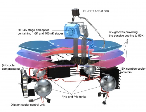
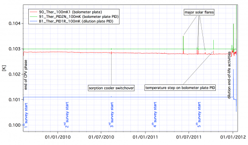
The HFI dilution cooler cools the bolometers down to 0.1 K through the dilution of 3He into 4He and the intermediate optical plate to 1.4 K through Joule-Thomson expansion of the 3He and 4He mixture. Two stages of proportional-integral-derivative (PID) regulation are included on the 0.1K stage. The first one (PID1) is at the dilution cold-end itself and provides stability on long timescales. When no thermal perturbation is applied to the bolometer plate, the PID1 alone provides the required stability. A passive thermal filter is mounted between the dilution cold end and the bolometer optical plate. It gives a thermal time constant of several hours between these stages. A second regulation system (PID2) is located on the bolometer plate, with a similar time constant. The dilution cooler is described in detail in section 2.3.3 of Planck-Early-II[1].
The dilution was operated with flows set to the minimum available values, providing a total lifetime of 30.5 months, exceeding the nominal lifetime of 16 months by 14.5 months. The dilution stage was stabilized by the PID1 at a temperature close to 101 mK using 20 to 30 nW of power. The bolometer plate was stabilized by the PID2 at 102.8 mK with about 5 nW of power. The cooling power values were in very good agreement with those obtained during the ground tests and calibration.
However, the cosmic particle interactions with the 0.1K stage induced both temperature fluctuations of the 0.1K plates and glitches on the thermometer measurements.
At very low frequency, below 1 mHz, the temperature fluctuations are very well correlated with the hit rate of high energy particles, as measured by the on-board Standard Radiation Environment Monitor (SREM). At frequencies in the 10 mHz to 1 Hz range, single events inducing a global or partial temperature change of the bolometer plate are observed. Decorrelation of the bolometer signal from the thermal fluctuations is described in the TOI processing section.
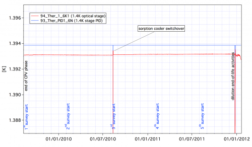
The 1.4-K stage is very stable and given the very low coupling coefficients between the 1.4-K optical components and the detectors no effect can be measured on the signal. Detailed thermal analysis of the in-flight stability of the dilution cooler can be found in section 5.4 of Planck-Early-II[1].
The 4-K J-T cooler[edit]
The HFI 4-K Joule-Thomson (J-T) cooler produces a temperature of 4 K for the HFI 4-K stage and optics and the precooling of the dilution gases. Full description of the 4-K cooler can be found in section 2.3.2 of Planck-Early-II[1].
The two mechanical compressors produce micro-vibrations and also induce electromagnetic interference affecting the science signals of bolometers. The risks associated with these effects were taken into account early in the design of the HFI by phase-locking the sample frequency of the data to a harmonic of the compressor frequency. The removal of these interference effects is addressed in the 4-K cooler lines variability section.
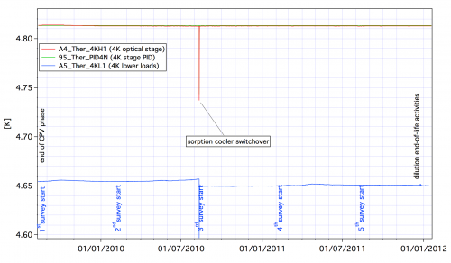
Operation of the 4-K J-T cooler was flawless during the whole mission, except for an unexpected shutdown during the CPV on August 6th 2009, caused by an SEU on the precharge regulator. This never occured again, and the 4-K J-T cooler was then operated without interruption during the entire survey phase of the mission. It remained in operation throughout the "warm mission", since it also provided the cooling of the optical reference loads of the LFI.
The 4-K J-T cooler compressor amplitude was set to 3450 μm during the CPV, and was maintained to this value during the entire mission. Its cooling power was very stable and gave enough margin to cancel out the fluctuations and drifts induced by the sorption cooler fluctuations and adjustments. The PID stabilizing the temperature of the HFI optics was regulated at 4.81 K using a power around 1.8 mW.
Details of the in-flight performance of the 4-K J-T cooler can be found in in section 5.3 of Planck-Early-II[1].
References[edit]
- ↑ Jump up to: 1.01.11.21.3 Planck early results. II. The thermal performance of Planck, Planck Collaboration II, A&A, 536, A2, (2011).
(Planck) High Frequency Instrument
Space Radiation Environment Monitor
Calibration and Performance Verification
(Planck) Low Frequency Instrument


