Difference between revisions of "Beams LFI"
(→Main Beams and Focal Plane calibration) |
(→Main Beams and Focal Plane calibration) |
||
| Line 20: | Line 20: | ||
== Main Beams and Focal Plane calibration == | == Main Beams and Focal Plane calibration == | ||
| − | + | The beam solid angle, Ω<math>_A </math>, of an antenna is given by | |
: <math> Ω_A \; = \; \int_{4π} \; P_n(θ,φ) \; dΩ \; = \; \int^{2π}_0 \int^π_0 \; P_n(θ,φ) \; sinθ \; dθ \; dφ </math> | : <math> Ω_A \; = \; \int_{4π} \; P_n(θ,φ) \; dΩ \; = \; \int^{2π}_0 \int^π_0 \; P_n(θ,φ) \; sinθ \; dθ \; dφ </math> | ||
\Omega | \Omega | ||
where <math>P_n (θ, φ) \; </math> is the normalized power pattern and the field computed by GRASP is normalised to a total power of 4π watt, i.e., | where <math>P_n (θ, φ) \; </math> is the normalized power pattern and the field computed by GRASP is normalised to a total power of 4π watt, i.e., | ||
: <math> \int^{2π}_0 \int^π_0 \; P_n(θ,φ) \; sinθ \; dθ \; dφ \; = \; 4π </math> | : <math> \int^{2π}_0 \int^π_0 \; P_n(θ,φ) \; sinθ \; dθ \; dφ \; = \; 4π </math> | ||
| − | |||
| − | |||
| − | |||
| − | |||
== Effective beams == | == Effective beams == | ||
Revision as of 11:17, 25 February 2013
Contents
Wish List[edit]
list of information to be inserted in the explanatory supplements
- Description of LFI FOV.
- Description of various telescope models as reported in the beam paper.
- Format of beam data
- Definition of various coordinate frames for beams
Overview[edit]
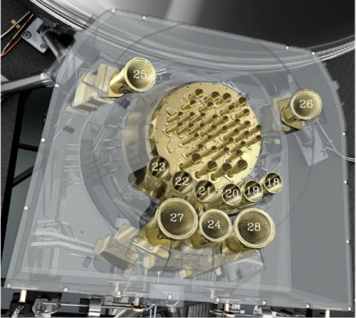
LFI is coupled to the telescope by eleven dual-profiled, corrugated, conical horns #sandri2010,villa2010: six feed horns at 70 GHz (FH18 – FH23), three feed horns at 44 GHz (FH24 – FH26), and two feed horns at 30 GHz (FH27 and FH28). Each feed horn is connected to an orthomode transducer (OMT) to divide the field propagating into the horn into two orthogonal linear polarization components, X and Y #darcangelo2010a.

The feeds and corresponding OMTs are adjusted in the focal surface so that the main beam polarization directions of the two symmetrically located feed horns in the focal plane unit (FPU) are at an angle of 45 degrees when observed in the same direction in the sky. This configuration permits measurement of the Q and U Stokes parameters and thus the linear polarization of the CMB.
Main Beams and Focal Plane calibration[edit]
The beam solid angle, Ω, of an antenna is given by
\Omega where is the normalized power pattern and the field computed by GRASP is normalised to a total power of 4π watt, i.e.,
Effective beams[edit]
TBW
Sidelobes[edit]
References[edit]
<biblio force=false>
</biblio>
(Planck) Low Frequency Instrument
Field-Of-View
LFI Ortho Module Transducer
(Planck) High Frequency Instrument
European Space Agency
Focal Plane Unit
Cosmic Microwave background