Difference between revisions of "Beams LFI"
(→Overview) |
(→Overview) |
||
| Line 15: | Line 15: | ||
Each beam of the radiometer pair (Radiometer Chain Assembly - RCA) is named as LFIXXM or LFIXXS. XX is the RCA number ranging from 18 to 28; M and S are the two polarization namely main-arm and side-arm of the Orthomode transduccers <cite>#darcangelo2009b</cite>. | Each beam of the radiometer pair (Radiometer Chain Assembly - RCA) is named as LFIXXM or LFIXXS. XX is the RCA number ranging from 18 to 28; M and S are the two polarization namely main-arm and side-arm of the Orthomode transduccers <cite>#darcangelo2009b</cite>. | ||
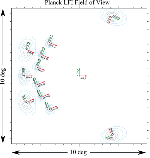
| − | [[File:fieldofview.png|500px|thumb|centre|Figure 1. A sketch of the Planck LFI field of view in the (u,v) plane is shown. The polarization direction on the sky are highlighted by the colored arrows. The M-polarization is shown in green and the S-polarization in red. | + | [[File:fieldofview.png|500px|thumb|centre|Figure 1. A sketch of the Planck LFI field of view in the (u,v) plane is shown. The polarization direction on the sky are highlighted by the colored arrows. The M-polarization is shown in green and the S-polarization in red. Main beam shapes are shown for completness and they are not representative of flight beams.]] |
| + | |||
| + | |||
| + | |||
| + | <!-- | ||
For the beam we consider these three regions: | For the beam we consider these three regions: | ||
| Line 23: | Line 27: | ||
; near sidelobes: is the pattern contained between the main beam angular limit and 5 degrees from the beam center (this is often called <b>intermediate beam</b>). | ; near sidelobes: is the pattern contained between the main beam angular limit and 5 degrees from the beam center (this is often called <b>intermediate beam</b>). | ||
; far sidelobes: is the pattern at angular regions more than 5 degrees from the beam center. | ; far sidelobes: is the pattern at angular regions more than 5 degrees from the beam center. | ||
| + | --> | ||
== Main Beams and Focal Plane calibration == | == Main Beams and Focal Plane calibration == | ||
Revision as of 14:17, 25 February 2013
Contents
Wish List[edit]
list of information to be inserted in the explanatory supplements
- Description of LFI FOV.
- Description of various telescope models as reported in the beam paper.
- Format of beam data
- Definition of various coordinate frames for beams
Overview[edit]
LFI is observing the sky with 11 pairs of beams associated with the 22 pseudo-correlation radiometers. Each beam of the radiometer pair (Radiometer Chain Assembly - RCA) is named as LFIXXM or LFIXXS. XX is the RCA number ranging from 18 to 28; M and S are the two polarization namely main-arm and side-arm of the Orthomode transduccers #darcangelo2009b.

Main Beams and Focal Plane calibration[edit]
Describe the RIMO content (beam section)
The beam solid angle, Ω, of an antenna is given by
\Omega where is the normalized power pattern and the field computed by GRASP is normalised to a total power of 4π watt, i.e.,
Effective beams[edit]
TBW
Window Functions[edit]
TBW
Sidelobes[edit]
TBW
References[edit]
<biblio force=false>
</biblio>
(Planck) Low Frequency Instrument
Field-Of-View
LFI Radiometer Chain Assembly