Difference between revisions of "The satellite WiP"
| Line 110: | Line 110: | ||
===The instruments=== | ===The instruments=== | ||
| − | |||
| + | The frequency range of the two Planck instruments together is designed to cover the peak of the CMB spectrum and to characterize the spectra of the main Galactic foregrounds (synchrotron and free-free emission at low frequencies, and dust emission at high frequencies). The LFI covers 30–70GHz in three bands, and the HFI covers 100–857 GHz in six bands. The band centers are spaced approximately logarithmically. The following figure shows the main elements of the instruments, including the cryogenic focal plane and the warm readout units. | ||
| − | + | [[File:12983f5b.jpg | 500px | center | thumb | '''An exploded view of the Planck instruments. ''']] | |
| − | |||
The LFI ({{PlanckPapers|bersanelli2010}}) is designed around 22 pseudo-correlation radiometers fed by corrugated feedhorns and ortho-mode transducers to separate two orthogonal linear polarisations. Each horn thus feeds two radiometers. The radiometers are based on front-end low noise amplifiers using indium-phosphide high electron mobility transistors, which process simultaneously the signal from the sky fed by the telescope, and the signal from stable blackbody reference loads located on the external body of the HFI where they can be maintained at a temperature of 4 K. The front-end amplifiers are located in the focal plane of the telescope, and are operated at a temperature of ∼20 K; they feed warm back-end amplifiers and detection electronics via waveguides connecting the FPU to the warm service module. For each radiometer, sky and load time-ordered data are separately reconstructed and made available for processing on the ground. | The LFI ({{PlanckPapers|bersanelli2010}}) is designed around 22 pseudo-correlation radiometers fed by corrugated feedhorns and ortho-mode transducers to separate two orthogonal linear polarisations. Each horn thus feeds two radiometers. The radiometers are based on front-end low noise amplifiers using indium-phosphide high electron mobility transistors, which process simultaneously the signal from the sky fed by the telescope, and the signal from stable blackbody reference loads located on the external body of the HFI where they can be maintained at a temperature of 4 K. The front-end amplifiers are located in the focal plane of the telescope, and are operated at a temperature of ∼20 K; they feed warm back-end amplifiers and detection electronics via waveguides connecting the FPU to the warm service module. For each radiometer, sky and load time-ordered data are separately reconstructed and made available for processing on the ground. | ||
| Line 120: | Line 119: | ||
The HFI {{PlanckPapers|lamarre2010}} is designed around 52 bolometers fed by corrugated feedhorns and bandpass filters within a back-to-back conical horn optical waveguide. Twenty of the bolometers (spider-web bolometers or SWBs) are sensitive to total power, and the remaining 32 units are arranged in pairs of orthogonally-oriented polarisation-sensitive bolometers (PSBs). All bolometers are operated at a temperature of ∼0.1 K, and read out by an AC-bias scheme through JFET amplifiers operated at ∼130 K. | The HFI {{PlanckPapers|lamarre2010}} is designed around 52 bolometers fed by corrugated feedhorns and bandpass filters within a back-to-back conical horn optical waveguide. Twenty of the bolometers (spider-web bolometers or SWBs) are sensitive to total power, and the remaining 32 units are arranged in pairs of orthogonally-oriented polarisation-sensitive bolometers (PSBs). All bolometers are operated at a temperature of ∼0.1 K, and read out by an AC-bias scheme through JFET amplifiers operated at ∼130 K. | ||
| − | The main parameters of the instruments, as derived from early in-flight operations, are summarized in the following table (from {{PlanckPapers|planck2011-1-1}}: | + | The main parameters of the instruments, as derived from early in-flight operations, are summarized in the following table (from {{PlanckPapers|planck2011-1-1}}): |
| − | [[File: | + | [[File:InstrumentPerfo.jpg | 500px | center | thumb | '''Planck performance parameters as determined from early flight data. ''']] |
For more information on the LFI and HFI instruments: | For more information on the LFI and HFI instruments: | ||
Revision as of 13:34, 19 October 2017
Contents
[hide]Overview[edit]
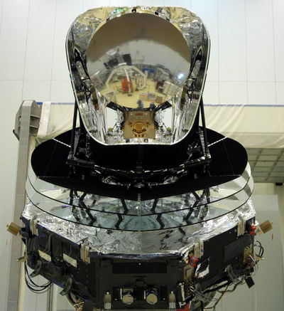
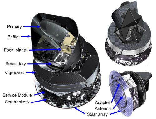
The figures below show the major elements and characteristics of the Planck satellite.
The Planck spacecraft was designed, built and tested around two major modules:
- The payload module containing: an off-axis telescope with a projected diameter of 1.5m, focussing radiation from the sky onto a focal plane shared by detectors of the LFI and HFI, operating at 20K and 0.1K, respectively; a telescope baffle that simultaneously provides stray-light shielding and radiative cooling; and three conical “V-groove” baffles that provide thermal and radiative insulation between the warm service module and the cold telescope and instruments.
- The service module containing all the warm electronics servicing instruments and spacecraft, and the solar panel providing electrical power. It also contains the cryocoolers, the main on-board computer, the telecommand receivers and telemetry transmitters, and the attitude control system with its sensors and actuators.
The most relevant technical characteristics of the Planck spacecraft are detailed in the Table below. A more complete technical description of the Planck satellite can be found here (link to excerpts from the Satellite User Manual).
| Diameter | 4.2 m | Defined by the solar array |
| Height | 4.2 m | |
| Total mass at launch | 1912 kg | Fuel mass = 385 kg at launch; He mass = 7.7 kg |
| Electrical power demand (avg) | 1300 W | Instrument part: 685 W (Begining of Life), 780 W (End of Life) |
| Minimum operational lifetime | 18 months | Planck operated for 32 months with both instruments; the LFI continued surveying the sky for an additional 20 months |
| Spin rate | 1 rpm | ±0.6 arcmin/sec (changes due to manoeuvers); stability during inertial pointing ≈6.5×10^-5 rpm/h |
| Max angle of spin axis to Sun | 10 deg | To maintain the payload in the shade; default angle is 7.5 deg |
| Max angle of spin axis to Earth | 15 deg | To allow communication with Earth |
| Angle between spin axis and telescope boresight | 85 deg | Max extent of FOV ≈8 deg |
| On-board data storage capacity | 32 Gbit | Two redundant units (only one is operational at any time) |
| Data transmission rate to ground (max) | 1.5 Mbps | Within 15 deg of Earth, using a 35-m ground antenna |
| Daily contact period | Between 2 and 4 hours (as required by operational needs) | Effective real-time science data acquisition bandwidth 130 kbps |
For more information, see Planck-Early-I[1].
The payload module[edit]
The telescope[edit]
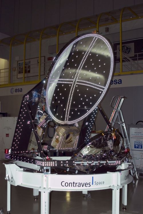
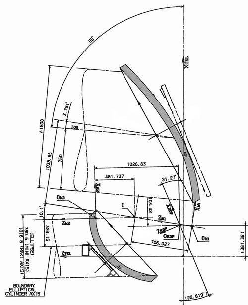
The telescope is an off-axis aplanatic design with two elliptical reflectors, a 1.5-m projected diameter, and an overall emissivity below about 1\%. The optical system was optimized for a set of representative detectors (eight HFI and eight LFI).
The Planck telescope assembly consists of:
- the primary and secondary reflectors (PR and SR), designed and manufactured by Astrium (Friedrichshafen, Germany);
- the support structure, designed and manufactured by Oerlikon Space (Zürich, Switzerland).
- the baffle2 surrounding the telescope, designed and manufactured by Contraves (Zürich, Switzerland)
- the third V-groove which forms the floor of the cavity in
which the telescope and focal plane are located, designed and manufactured by Thales Alenia Space (Cannes, France).
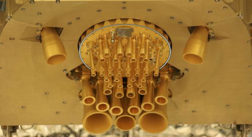
The telescope focusses radiation from the sky onto the focal plane, which consists of arrays of detector feedhorns, designed, manufactured and tested by the LFI and HFI instrument teams (Villa et al. 2009, Sandri et al. 2009, Maffei et al. 2009).
A more detailed description of the Planck telescope can be found in Planck-PreLaunch-II[2]. The in-flight performance of the telescope is investigated in (XXX).
The instruments[edit]
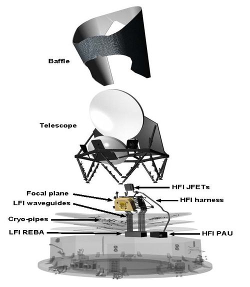
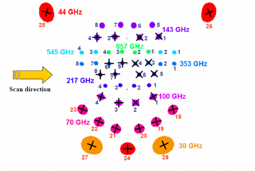
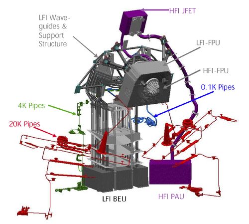
The frequency range of the two Planck instruments together is designed to cover the peak of the CMB spectrum and to characterize the spectra of the main Galactic foregrounds (synchrotron and free-free emission at low frequencies, and dust emission at high frequencies). The LFI covers 30–70GHz in three bands, and the HFI covers 100–857 GHz in six bands. The band centers are spaced approximately logarithmically. The following figure shows the main elements of the instruments, including the cryogenic focal plane and the warm readout units.
The LFI (Planck-PreLaunch-IV[3]) is designed around 22 pseudo-correlation radiometers fed by corrugated feedhorns and ortho-mode transducers to separate two orthogonal linear polarisations. Each horn thus feeds two radiometers. The radiometers are based on front-end low noise amplifiers using indium-phosphide high electron mobility transistors, which process simultaneously the signal from the sky fed by the telescope, and the signal from stable blackbody reference loads located on the external body of the HFI where they can be maintained at a temperature of 4 K. The front-end amplifiers are located in the focal plane of the telescope, and are operated at a temperature of ∼20 K; they feed warm back-end amplifiers and detection electronics via waveguides connecting the FPU to the warm service module. For each radiometer, sky and load time-ordered data are separately reconstructed and made available for processing on the ground.
The HFI Planck-PreLaunch-IX[4] is designed around 52 bolometers fed by corrugated feedhorns and bandpass filters within a back-to-back conical horn optical waveguide. Twenty of the bolometers (spider-web bolometers or SWBs) are sensitive to total power, and the remaining 32 units are arranged in pairs of orthogonally-oriented polarisation-sensitive bolometers (PSBs). All bolometers are operated at a temperature of ∼0.1 K, and read out by an AC-bias scheme through JFET amplifiers operated at ∼130 K.
The main parameters of the instruments, as derived from early in-flight operations, are summarized in the following table (from Planck-Early-I[1]):
For more information on the LFI and HFI instruments:
- A more complete overview of the two Planck instruments can be found here: HFI, LFI.
- A detailed technical description of the instruments can be found in the User Manuals (link to User Manuals).
- A detailed description of the LFI design and performance as measured on the ground can be found in Planck-PreLaunch-IV[3], Planck-PreLaunch-V[5], and other related papers. Descriptions of the LFI's in-orbit performance can be found in Planck-2020-A2[6], Planck-2015-A02[7] and associated papers, Planck-2013-II[8] and associated papers, and Planck-Early-III[9].
- Detailed descriptions of the HFI design and performance as measured on the ground are included in Planck-PreLaunch-IX[4], Planck-PreLaunch-X[10], and other related papers. Descriptions of the HFI's in-orbit performance can be found in Planck-2020-A3[11], Planck-2015-A07[12] and Planck-2015-A08[13], [14], and Planck-Early-IV[15].
The service module[edit]
The service module provides the various equipment and instruments housed in it with suitable mechanical and thermal environments during launch and orbit. It is formed by an octagonal box, built around a conical tube, which supports the following subsystems intervening in flight operations:
- Command and data management;
- Attitude control and measurement;
- Power control;
- Reaction control;
- Telemetry, tracking and command;
- Thermal control.
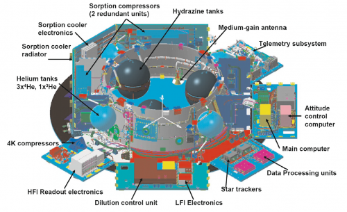
The service module contains all the warm satellite and payload electronic units, with the only exception of the box containing JFETs for impedance-matching to the HFI bolometers, which is mounted on the primary reflector support panel, to allow the operation of the JFETs at an optimal temperature of around 130 K. The service module holds:
- Main computer;
- Attitude control computer;
- Data processing units;
- Star trackers;
- LFI electronics;
- Dilution control unit;
- HFI readout electronics;
- 4K compressors;
- Helium tanks, 36000 litres of 4He, and 12000 litres of 3He gas stored in four high-pressure tanks;
- Sorption cooler radiator;
- Sorption cooler electronics;
- Sorption compressors (two redundant units);
- Hydrazine tanks;
- Medium-gain antenna;
- Telemetry subsystem.
For more information, see Planck-PreLaunch-I[16].
Thermal design and the cryo-chain[edit]
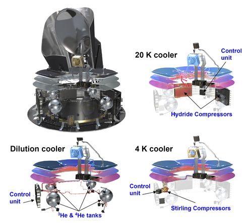
The cryogenic temperatures required by the detectors are achieved through a combination of passive radiative cooling and three active refrigerators. The contrast between the high power dissipation in the warm service module (∼1000 W at 300 K) and that at the coldest spot in the satellite (∼100 nW at 0.1 K) are testimony to the extraordinary efficiency of the complex thermal system which has to achieve such disparate ends simultaneously while preserving a very high level of stability at the cold end. The telescope baffle and V-groove shields are key parts of the passive thermal system. The baffle (which also acts as a stray-light shield) is a high-efficiency radiator consisting of ∼14 m2 of open aluminium honeycomb coated with black cryo- genic paint; the effective emissivity of this combination is very high (>0.9). The “V-grooves” are a set of three conical shields with an angle of 5◦ between adjacent shields; the surfaces (approx 10 m2 on each side) are specular (aluminum coating with an emissivity of ∼0.045) except for the outer (∼4.5 m2) area of the topmost V-groove which has the same high-emissivity coating as the baffle. This geometry provides highly efficient radiative coupling to cold space, and a high degree of thermal and radia- tive isolation between the warm spacecraft bus and the cold telescope, baffle, and instruments. The cooling provided by the passive system leads to a temperature of 40–45 K for the telescope and baffle. Table 3 lists temperature ranges predicted in flight for various parts of the satellite, based on a thermo-mechanical model which has been correlated to test results; the uncertainty in the prediction for elements in the cold payload is of order (+0.5 K, −2 K). The active refrigeration chain further reduces the detector temperatures to 20 K (LFI front-end low noise amplifiers) and 0.1 K (HFI bolometers) respectively. It is based on three distinct units working in series (see the figure below):
1. The 20 K hydrogen sorption cooler was designed and built expressly for Planck at NASA’s Jet Propulsion Laboratory (USA) (Bhandari et al. 2004; Pearson et al. 2006); it directly cools the LFI low-noise amplifiers to their operating temperature while providing pre-cooling for the HFI cooler chain. The sorption cooler consists of two cold redundant units, each including a six-element sorption compressor and a Joule-Thomson (JT) expansion valve. Each element of the compressor is filled with hydride material (La Ni4.78 Sn0.22) which alternately absorbs and releases hy- drogen gas under control of a heat source. The cooler pro- duces liquid hydrogen in two liquid-vapor heat-exchangers (LVHXs) whose temperatures are stabilized by hydrogen ab- sorption into three compressor elements. LVHX1 provides pre-cooling for the HFI 4K cooler, while LVHX2 cools the LFI focal plane unit (FPU). The vapor pressure of the liquid hydrogen in the LVHXs is determined primarily by the absorption isotherms of the hydride material used in the compressor elements. Thus, the heat rejection temperature of the compressor elements determines the instrument temper- atures. On the spacecraft the compressor rejects heat to a radiator to space with flight allowable temperatures be- tween 262 and 282 K; the radiator is a single unit which couples the active and redundant sorption coolers via a net- work of heat pipes. The operating efficiency of the Planck sorption cooler depends on passive cooling by radiation to space, which is accomplished by heat exchange of the gas piping to the three V-groove radiators. The final V-groove is required to be between 45 and 60 K to provide the required cooling power for the two instruments. At the expected op- erating temperature of ∼47 K, with a working pressure of 3.2 MPa, the two sorption coolers produce the 990 mW of required cooling power for the two instruments, with a margin of ∼100 mW. The temperature in flight at the heat exchang- ers will be 17.5 K (LVHX1) and 19 K (LVHX2). LVHX2 is actively stabilised by a closed loop heat control; typical temperature fluctuation spectra are shown in Fig. 8.
2. The 4 K Joule-Thomson cooler is based on the closed circuit JT expansion of helium, driven by two mechanical compressors, one for the high pressure side and one for the low pressure side. A description of this system is given in Bradshaw et al. (1997). Similar compressors have already been used for active cooling at 70 K in space. The Planck 4 K cooler was initially developed under an ESA programme to provide 4 K cooling with reduced vibration for the FIRST (now Herschel) satellite. For this reason the two compressors are mounted in a back-to-back configuration, which cancels most of the mo- mentum transfer to the spacecraft. Furthermore, force trans- ducers placed between the two compressors provide an error signal which is used by the drive electronics servo sys- tem to control the motion profile of the pistons up to the 7th harmonic of the base compressor frequency (∼40 Hz). The damping of vibration achieved by this system is more than two orders of magnitude at the base frequency and fac- tors of a few at higher harmonics; the residual vibration lev- els will have a minor heating effect on the 100 mK stage, and negligible impact on the pointing. Pre-cooling of the he- lium is provided by the sorption cooler described above. The cold end of the cooler consists of a liquid helium reservoir located just behind the JT orifice. This cold tip is attached to the bottom of the 4 K box of the HFI FPU (see Fig. 7). It provides cooling for this screen and also pre-cooling for the gas in the dilution cooler pipe described later in this sec- tion. The margin between heat lift and heat load depends sensitively on the pre-cooling temperature provided by the sorption cooler at the LVHX1 interface. The temperature of LVHX1 is thus the most critical interface of the HFI cryo- genic chain; system-level tests have shown that it is likely to be ∼17.5 K, about 2 K below the maximum requirement3. At this pre-cooling temperature the heat load is 10.6 mW and the heat lift is 16.1 mW for a compressor stroke amplitude of 3.5 mm (the maximum is 4.4 mm). The heat load of the 4 K cooler onto the sorption cooler is only 30 mW, a very small amount with respect to the heat lift of the sorption cooler (990 mW); thus there is little back reaction of the 4 K onto the sorption cooler.
3. The dilution cooler consists of two cooling stages in series, using 36000 litres of He and 12000 litres of He gas stored on-board in 4 high-pressure tanks. The first stage is based on JT expansion, and produces cooling for the 1.6 K screen of the FPU and for pre-cooling of the second stage cooler. The latter is based on a dilution cooler principle working at zero-G, which was invented and tested by A. Benoît (Benoît et al. 1997), and developed into a space-qualified system by the Institut d’ A strophysique Spatiale (Orsay) and DTA Air Liquide (Grenoble), see Triqueneaux et al. (2006). The gas from the tanks (at 300 bars at the start of the mission) is brought down to 19 bars through a pressure regulator and the flow through the dilution is regulated by a set of discrete restrictions which can be switched by telecommand. The gas is vented to space after the dilution process4, and the cooler therefore has a lifetime limited by the gas supply. The dilution of the two helium isotopes provides the cooling of the bolome- ters to a temperature around 100 mK which is required to deliver a very high sensitivity for the channels near the peak of the CMB spectrum (noise equivalent power around −17 W/√Hz), limited mostly by the background photon noise.
The flight system was at ambient temperature at launch and cooled in space to operating conditions. The HFI bolometer plate reached 93 mK on 3 July 2009, 50 days after launch. The solar panel always faced the Sun, shadowing the rest of Planck, and operated at a mean temperature of 384 K. At the other end of the spacecraft, the telescope baffle operated at 42.3 K and the telescope primary mirror operated at 35.9 K. The temperatures of key parts of the instruments were stabilized by both active and passive methods. Temperature fluctuations were driven by changes in the distance from the Sun, sorption cooler cycling and fluctuations in gas-liquid flow, and fluctuations in cosmic ray flux on the dilution and bolometer plates. These fluctuations did not compromise the science data.
More details on the thermal design of the Planck satellite can be found in Planck-Early-II[17]. A detailed description of the cooling system and its performance in flight ...
Pointing[edit]
Planck spins at 1 rpm around the axis of symmetry of the solar panel2. In flight, the solar panel can be pointed within a cone of 10◦ around the direction to the Sun; everything else is always in its shadow. The attitude control system relies principally on:
- Redundant star trackers as main sensors, and solar cells for rough guidance and anomaly detection. The star trackers contain CCDs which are read out in synchrony with the speed of the field-of-view across the sky to keep star images compact.
- Redundant sets of hydrazine 20 N thrusters for large ma- noeuvers and 1 N thrusters for fine manoeuvers.
An on-board computer dedicated to this task reads out the star trackers at a frequency of 4 Hz, and determines in real time the absolute pointing of the satellite based on a catalogue of bright stars. Manoeuvers are carried out as a sequence of 3 or 4 thrusts spaced in time by integer spin periods, whose duration is calculated on-board, with the objective to achieve the requested atti- tude with minimal excitation of nutation. There is no further active damping of nutation during periods of inertial pointing, i.e. between manoeuvers. The duration of a small manoeuver typi- cal of routine operations (2 arcmin) is ∼5 min. Larger manoeuvers are achieved by a combination of thrusts using both 1 N and 20 N thrusters, and their duration can be considerable (up to several hours for manoeuver amplitudes of several degrees). The attitudes measured on-board are further filtered on the ground to reconstruct with high accuracy the spacecraft attitude (or rather the star tracker reference frame). The star trackers and the in- strumental field-of-view were aligned on the ground indepen- dently to the spacecraft reference frame; the resulting alignment accuracy between the star trackers and the instruments was of 0.19, far better than required. The angles between the star tracker frame and each of the detectors are determined in flight from observations of planets. Several bright planets drift through the field-of-view once every 6 months, providing many calibration points every year. There are many weaker point sources, both celestial and in the Solar System, which provide much more fre- quent though less accurate calibration tests. The in-flight pointing calibration is very robust vis-à-vis the expected thermoelastic deformations (which contribute a total of 0.14 arcmin to the total on-ground alignment budget). The most important pointing performance aspects, based on a realistic simulation using rather conservative parameter values, and tests of the attitude control system, are summarised in Table 2.
The 20 N thrusters are also used for orbit control manoeuvers during transfer to the final Planck orbit (two large manoeuvers planned) and for orbit maintenance (typically one manoeuver per month). Most of the hydrazine thruster fuel that Planck carries is expended in the two large manoeuvers carried out during trans- fer, and a very minor amount is required for orbit maintenance.
Additional instruments[edit]
The Standard Radiation Environment Monitor[edit]
The standard radiation environment monitor (SREM)[18] is a particle detector developed for satellite applications. It measures high-energy electrons and protons of the space environment with 20 angular resolution, as well as spectral information, and provides the host spacecraft with radiation data. SREM was developed and manufactured by Contraves Space in cooperation with the Paul Scherrer Institute under a development contract of the European Space Agency. SREM is the second generation of instruments in a programme that was established by ESA’s European Research and Technology Centre (ESTEC) to:
- provide minimum intrusive radiation detectors for space applications;
- provide radiation hazard alarm function to instruments on board spacecraft;
- assist in investigation activities related to possible radiation-related anomalies observed on spacecraft;
- assist in in-flight Technology Demonstration Activities.
The design goals are low weight, small dimensions, and low power consumption, combined with the ability to provide particle species and spectral information.
In the case of Planck, the use of the SREM was entirely within the scope of bullets 1 and 3 above, since, due to the nature of operations, no real time alarms were possible
The SREM consists of three detectors (D1, D2, and D3) in two detector head configurations. One system is a single silicon diode detector (D3). The main entrance window is covered with 0.7 mm aluminum, which defines the lower energy threshold for electrons to about 0.5 MeV and for protons to about 10MeV. The other system uses two silicon diodes (detectors D1/D2) arranged in a telescope configuration. The main entrance of this detector is covered with 2 mm of aluminium giving a proton and electron threshold of 20 and 1.5 MeV, respectively. A 1.7-mm-thick aluminium and 0.7–mm-thick tantalum layer separate the two diodes of the telescope configuration.
The telescope detector allows measurement of the high-energy proton fluxes with enhanced energy resolution. In addition, the shielding between the two diodes in the telescope prevents the passage of electrons. However, protons with energies greater than about 30 MeV go through. Thus, using the two diodes in coincidence gives pure proton count rates, allowing subtraction of the proton contribution from the electron channels. A total of 15 discriminator levels (see table below) are available to bin the energy of the detected
events.
| Name | Logic | Particle | Energy [MeV] |
|---|---|---|---|
| TC1 | D1 | protons | >20 |
| S12 | D1 | protons | 20 - 550 |
| S13 | D1 | protons | 20 - 120 |
| S14 | D1 | protons | 20 - 27 |
| S15 | D1 | protons | 20 - 34 |
| TC2 | D2 | protons | >39 |
| S25 | D2 | ions | 150 - 185 |
| C1 | D1D2 | coinc. protons | 40 - 50 |
| C2 | D1D2 | coinc. protons | 50 - 70 |
| C3 | D1D2 | coinc. protons | 70 - 120 |
| C4 | D1D2 | coinc. protons | >130 |
| TC3 | D3 | electrons | >0.5 |
| S32 | D3 | electrons | 0.55 - 2.3 |
| S33 | D3 | protons | 11 - 90 |
| S34 | D3 | protons | 11 - 30 |
| PL1 | D1 | Dead Time | NA |
| PL2 | D2 | Dead Time | NA |
| PL3 | D3 | Dead Time | NA |
The detector electronics are capable of processing a detection rate of 100 kHz with dead-time correction below 20%. The SREM is contained in a single box of size 20cm × 12cm × 10cm and weighs 2.6 kg. The box contains the detector systems with the analogue and digital front-end electronics, a power supply, and a TTC-B-01 telemetry and Telecommand interface protocol. By virtue of a modular buildup, the interface can be adapted to any spacecraft system. The power consumption is approximately 2.5 W. An essential input for the interpretation of the detection rates, in terms of particle fluxes, are the energy dependent
The SREM data are provided in the Planck Legacy Archive in the form of individual FITS files per calendar day. The SREM data are described here.
The Fibre-optic gyro unit[edit]
The fibre-optic gyro unit (FOG) is an extra payload on-board Planck, which is not used as part of the attitude control system. The FOG functioning is based on the physical phenomenon called the Sagnac effect::
"a solid-state optical interferometer enclosing a surface located on a rotating support will detect a phase difference of the optical signal, which is proportional to the angular rate and to the surface enclosed by the optical path".
The FOG features the following architecture.
- An optical path enclosing a maximal surface: this is realized through the 1 km long fibre optic, wound many times round, in order to make a reasonable sized interferometer (< 120 mm in diameter).
- A source, to deliver the light to the interferometer.
- A multifunction Integrated Optical Circuit, which closes the interferometer, to share the light between the two extremities of the fibre-optic coil, to filter undesirable polarization.
- A coupler to extract the optical signal coming back from the ring interferometer, which is the signal carrying the Sagnac inertial information, and to direct it towards an optical detector.
- A detection module to convert this light signal into an electrical signal.
- A closed-loop signal processing system to increase the dynamic range and remove the effect of fluctuations of the optical power and of the gain of the detection chain, allowing an easy auto-calibration of the system and excellent scale factor stability and linearity.
- A biasing modulation allowing the measurement of very low rotation rates as well as the sign of those rotations.
Redundancy is offered by providing four skewed gyro channels, allowing the Attitude Control and Measurement Subsystem to use any triplet among the four axes to determine the spacecraft three axis rates. Nominally the four channels are activated, but in case of failure or critical thermal situations a subset of channels could be used.
There is no dangerous FOG flight command. The FOG is designed to operate five years ON in orbit, withstanding 1000 ON/OFF cycles, and its performance is guaranteed under rotations of deg/second, and over the temperature range of 253 K to 333 K. Power dissipation levels are in the range of 5.5 to 6.7 W/channel.
References[edit]
- ↑ Jump up to: 1.01.1 Planck early results. I. The Planck mission, Planck Collaboration I, A&A, 536, A1, (2011).
- Jump up ↑ Planck pre-launch status: The optical system, J. A. Tauber, H. U. Nørgaard-Nielsen, P. A. R. Ade, et al. , A&A, 520, A2+, (2010).
- ↑ Jump up to: 3.03.1 Planck pre-launch status: Design and description of the Low Frequency Instrument, M. Bersanelli, N. Mandolesi, R. C. Butler, et al. , A&A, 520, A4+, (2010).
- ↑ Jump up to: 4.04.1 Planck pre-launch status: The HFI instrument, from specification to actual performance, J.-M. Lamarre, J.-L. Puget, P. A. R. Ade, et al. , A&A, 520, A9+, (2010).
- Jump up ↑ Planck pre-launch status: Low Frequency Instrument calibration and expected scientific performance, A. Mennella, M. Bersanelli, R. C. Butler, et al. , A&A, 520, A5+, (2010).
- Jump up ↑ Planck 2018 results. II. Low Frequency Instrument data processing, Planck Collaboration, 2020, A&A, 641, A2.
- Jump up ↑ Planck 2015 results. II. LFI processing, Planck Collaboration, 2016, A&A, 594, A2.
- Jump up ↑ Planck 2013 results. II. Low Frequency Instrument data processing, Planck Collaboration, 2014, A&A, 571, A2.
- Jump up ↑ Planck early results. III. First assessment of the Low Frequency Instrument in-flight performance, A. Mennella, R. C. Butler, A. Curto, et al. , A&A, 536, A3, (2011).
- Jump up ↑ Planck pre-launch status: HFI ground calibration, F. Pajot, P. A. R. Ade, J.-L. Beney, et al. , A&A, 520, A10+, (2010).
- Jump up ↑ Planck 2018 results. III. High Frequency Instrument data processing and frequency maps, Planck Collaboration, 2020, A&A, 641, A3.
- Jump up ↑ Planck 2015 results. VII. High Frequency Instrument data processing: Time-ordered information and beam processing, Planck Collaboration, 2016, A&A, 594, A7.
- Jump up ↑ Planck 2015 results. VIII. High Frequency Instrument data processing: Calibration and maps, Planck Collaboration, 2016, A&A, 594, A8.
- Jump up ↑
- Jump up ↑ Planck early results, IV. First assessment of the High Frequency Instrument in-flight performance, Planck HFI Core Team, A&A, 536, A4, (2011).
- Jump up ↑ Planck pre-launch status: The Planck mission, J. A. Tauber, N. Mandolesi, J.-L. Puget, et al. , A&A, 520, A1+, (2010).
- Jump up ↑ Planck early results. II. The thermal performance of Planck, Planck Collaboration II, A&A, 536, A2, (2011).
- Jump up ↑ The ESA Standard Radiation Environment Monitor program first results from PROBA-I and INTEGRAL, A. Mohammadzadeh, H. Evans, P. Nieminen, E. Daly, P. Vuilleumier, P. Buhler, C. Eggel, W. Hajdas, N. Schlumpf, A. Zehnder, J. Schneider, R. Fear, Nuclear Science, IEEE Transactions on, 50, 2272-2277, (Dec.).
(Planck) Low Frequency Instrument
(Planck) High Frequency Instrument
revolutions per minute
Field-Of-View
Cosmic Microwave background
Focal Plane Unit
Junction Field Elect Transistor
European Space Agency
Space Radiation Environment Monitor
European Space TEchnology and Research Centre
Flexible Image Transfer Specification
Fiber Optic Gyroscope
