Difference between revisions of "The satellite"
(→Thermal design) |
|||
| Line 62: | Line 62: | ||
For more information, see <cite>#planck2011-1-1</cite>. | For more information, see <cite>#planck2011-1-1</cite>. | ||
| + | |||
| + | ==The service module== | ||
| + | The service module provides the various equipment and instruments housed in it with suitable mechanical and thermal environments during launch and orbit. It is formed by an octagonal box, built around a conical tube, which supports the following subsystems intervening in flight operations: | ||
| + | *Command and data management. | ||
| + | *Attitude control and measurement. | ||
| + | *Power control. | ||
| + | *Reaction control. | ||
| + | *Telemetry, tracking and command. | ||
| + | *Thermal control. | ||
| + | |||
| + | The service module contains all the warm satellite and payload electronic units, with the only exception of the box containing JFETs for impedance-matching to the HFI bolometers, which is mounted on the primary reflector support panel, to allow the operation of the JFETs at an optimal temperature of ∼130 K. The service module holds: | ||
| + | *Main computer | ||
| + | *Attitude control computer | ||
| + | *Data processing units | ||
| + | *Star trackers | ||
| + | *LFI electronics | ||
| + | *Dilution control unit | ||
| + | *HFI readout electronics | ||
| + | *4K compressors | ||
| + | *Helium tanks: 36000 litres of <math>^{4}</math>He, and 12000 litres of <math>^{3}</math>He gas are stored in four high-pressure tanks. | ||
| + | *Sorption cooler radiator | ||
| + | *Sorption cooler electronics | ||
| + | *Sorption compressors (2 redundant units) | ||
| + | *Hydrazine tanks | ||
| + | *Medium-gain antenna | ||
| + | *Telemetry subsystem. | ||
| + | |||
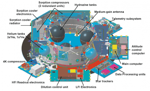
| + | [[File:SVM.png | 500px | center | thumb | '''The Planck service module. Figure courtesy of Thales Alenia Space (France).''']] | ||
| + | |||
| + | For more information, see <cite>#tauber2010a</cite>. | ||
==Thermal design== | ==Thermal design== | ||
| Line 68: | Line 98: | ||
The contrast between the high power dissipation in the warm service module (<math>\sim</math> 1000 W at 300 K) and that at the coldest spot in the satellite (<math>\sim</math>100 nW at 0.1 K) are testimony to the extraordinary efficiency of the complex thermal system which has to achieve such disparate ends simultaneously while preserving a very high level of stability at the cold end. More details on the thermal design of the Planck satellite can be found in the {{PEarly|2}}. | The contrast between the high power dissipation in the warm service module (<math>\sim</math> 1000 W at 300 K) and that at the coldest spot in the satellite (<math>\sim</math>100 nW at 0.1 K) are testimony to the extraordinary efficiency of the complex thermal system which has to achieve such disparate ends simultaneously while preserving a very high level of stability at the cold end. More details on the thermal design of the Planck satellite can be found in the {{PEarly|2}}. | ||
| + | ==The instruments== | ||
| + | A complete technical description of the teo Planck instruments can be found here: [[HFI design, qualification and performance|HFI]], [[LFI_Overview|LFI]] | ||
==References== | ==References== | ||
<biblio force=false> | <biblio force=false> | ||
Revision as of 11:29, 15 March 2013
Overview[edit]
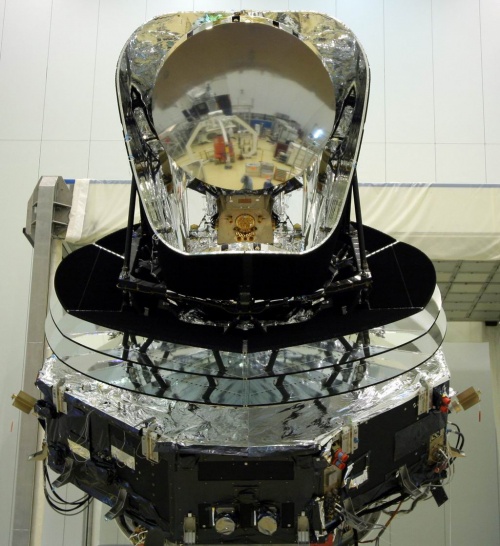
The Planck satellite was designed, built and tested around two major modules:
- The payload module containing an off-axis telescope with a projected diameter of 1.5m, focussing radiation from the sky onto a focal plane shared by detectors of the LFI and HFI, operating at 20K and 0.1K respectively; a telescope baffle that simultaneously provides stray-light shielding and radiative cooling; and three conical “V-groove” baffles that provide thermal and radiative insulation between the warm service module and the cold telescope and instruments.
- The service module containing all the warm electronics servicing instruments and satellite; and the solar panel providing electrical power. It also contains the cryocoolers, the main on-board computer, the telecommand receivers and telemetry transmitters, and the attitude control system with its sensors and actuators. The most relevant technical characteristics of the Planck spacecraft are detailed in the Table bellow.
Table. Planck satellite characteristics.
| Diameter | 4.2 m | Defined by the solar array |
| Height | 4.2 m | |
| Total mass at launch | 1912 kg | Fuel mass = 385 kg at launch; He mass = 7.7 kg |
| Electrical power demand (avg) | 1300 W | Instrument part: 685 W (Begining of Life), 780 W (End of Life) |
| Minimum operational lifetime | 18 months | Planck operated for 32 months with both instruments; the LFI continues surveying the sky |
| Spin rate | 1 rpm | $\pm 0.6$ arcmin/sec (changes due to manoeuvers); stability during inertial pointing rpm/h |
| Max angle of spin axis to Sun | 10 deg | To maintain the payload in the shade; default angle is 7.5 deg |
| Max angle of spin axis to Earth | 15 deg | To allow communication to Earth |
| Angle between spin axis and telescope boresight | 85 deg | Max extent of FOV∼ 8 deg |
| On-board data storage capacity | 32 Gbit | Two redundant units (only one is operational at any time) |
| Data transmission rate to ground (max) | 1.5 Mbps | Within 15 deg of Earth, using a 35 m ground antenna |
| Daily contact period | 3 h | The effective real-time science data acquisition bandwidth is 130 kbps |
For more information, see #planck2011-1-1.
The service module[edit]
The service module provides the various equipment and instruments housed in it with suitable mechanical and thermal environments during launch and orbit. It is formed by an octagonal box, built around a conical tube, which supports the following subsystems intervening in flight operations:
- Command and data management.
- Attitude control and measurement.
- Power control.
- Reaction control.
- Telemetry, tracking and command.
- Thermal control.
The service module contains all the warm satellite and payload electronic units, with the only exception of the box containing JFETs for impedance-matching to the HFI bolometers, which is mounted on the primary reflector support panel, to allow the operation of the JFETs at an optimal temperature of ∼130 K. The service module holds:
- Main computer
- Attitude control computer
- Data processing units
- Star trackers
- LFI electronics
- Dilution control unit
- HFI readout electronics
- 4K compressors
- Helium tanks: 36000 litres of He, and 12000 litres of He gas are stored in four high-pressure tanks.
- Sorption cooler radiator
- Sorption cooler electronics
- Sorption compressors (2 redundant units)
- Hydrazine tanks
- Medium-gain antenna
- Telemetry subsystem.
For more information, see #tauber2010a.
Thermal design[edit]
The performance of the Planck instruments in space is enabled by their low operating temperatures, 20 K for LFI and 0.1 K for HFI, achieved through a combination of passive radiative cooling and three active coolers. The scientific requirement for very broad frequency coverage led to two detector technologies with widely different temperature and cooling needs. Active coolers could satisfy these needs; a helium cryostat, as used by previous cryogenic space missions (IRAS, COBE, ISO, Spitzer, AKARI), could not. Radiative cooling is provided by three V-groove radiators and a large telescope baffle. The active coolers are a hydrogen sorption cooler (<20 K), a He Joule-Thomson cooler (4.7 K), and a He-He dilution cooler (1.4 K and 0.1 K). The flight system was at ambient temperature at launch and cooled in space to operating conditions. The HFI bolometer plate reached 93 mK on 3 July 2009, 50 days after launch. The solar panel always faces the Sun, shadowing the rest of Planck, and operates at a mean temperature of 384 K. At the other end of the spacecraft, the telescope baffle operates at 42.3 K and the telescope primary mirror operates at 35.9 K. The temperatures of key parts of the instruments are stabilized by both active and passive methods. Temperature fluctuations are driven by changes in the distance from the Sun, sorption cooler cycling and fluctuations in gas-liquid flow, and fluctuations in cosmic ray flux on the dilution and bolometer plates. These fluctuations do not compromise the science data.
The contrast between the high power dissipation in the warm service module ( 1000 W at 300 K) and that at the coldest spot in the satellite (100 nW at 0.1 K) are testimony to the extraordinary efficiency of the complex thermal system which has to achieve such disparate ends simultaneously while preserving a very high level of stability at the cold end. More details on the thermal design of the Planck satellite can be found in the Planck early paper II .
The instruments[edit]
A complete technical description of the teo Planck instruments can be found here: HFI, LFI
References[edit]
<biblio force=false>
</biblio>
(Planck) Low Frequency Instrument
(Planck) High Frequency Instrument
revolutions per minute
Field-Of-View

