Spectral response
HFI Spectral Response[edit]
This section outlines the unit conversion and colour correction protocol for Planck/HFI. Tables of unit conversion and colour correction coefficients will be included (there is not room for these in the P03d Co-Paper). Some of the checks on the unit conversion and colour correction coefficients will be described here also. Planet colour correction coefficients will be provided here (or perhaps in the joint HFI/LFI section). There will be links to the UcCC subsection of the PLA section, but the numbers and details belong here. The PLA UcCC subsection is primarily to introduce the software tools.
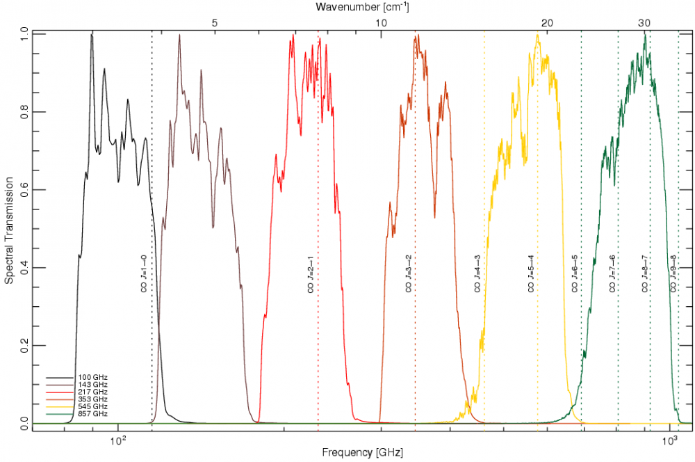
The band-average HFI spectral response data are shown in the figure below, and provided in the RIMO file (here).
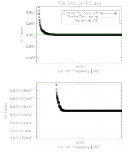
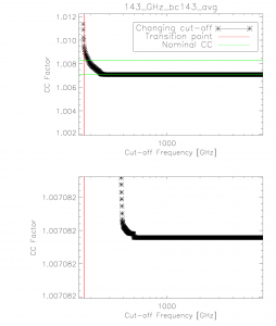
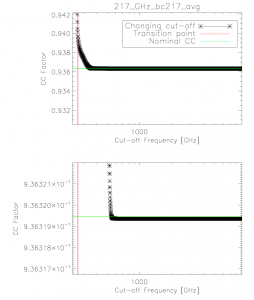
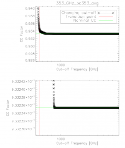
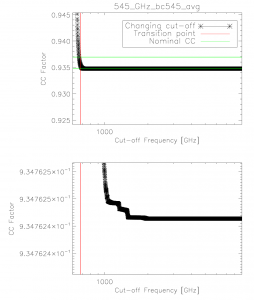
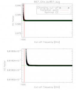
The integration ranges used in determining the unit conversion and colour correction coefficients are verified through an iterative approach starting at one extreme and reducing to the band-centre for both the low and high frequency edges. The figure below demonstrates the stability in the integral once a sufficient data range has been employed. The range used in the official coefficients is thus sufficient to ensure that it falls within the flat region of the demonstration figure below.
Colour Correction (alpha = -1 to +2) stability with integration cut-off variation. The horizontal bars illustrate the nominal colour correction values. Similar results are found for the integration cut-on.
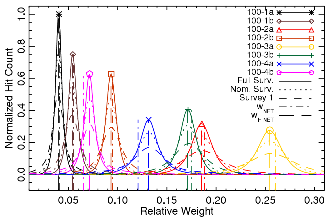
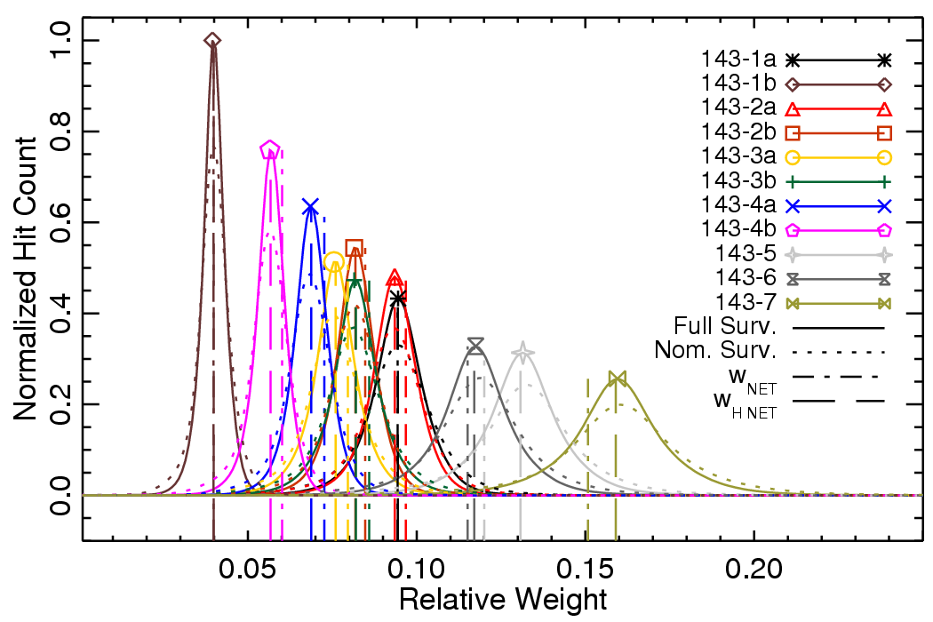
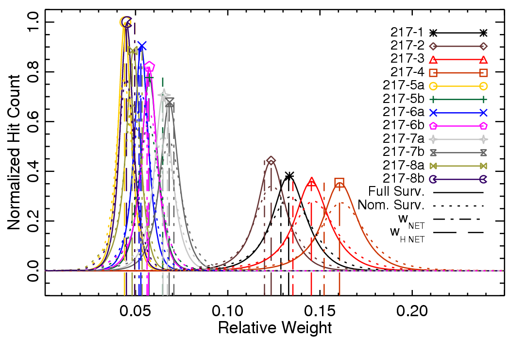
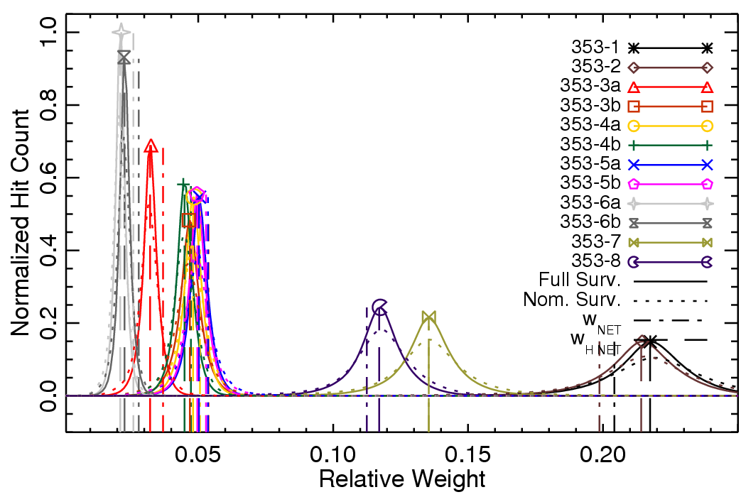
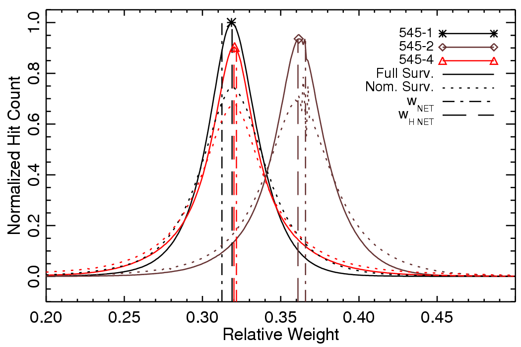
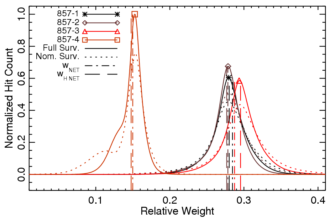
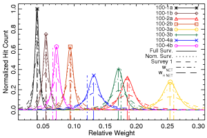
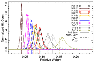
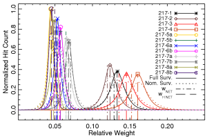
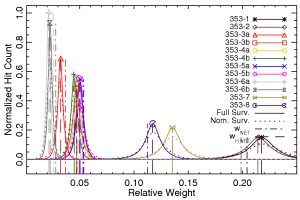
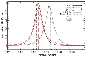
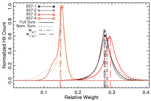
The band-average spectrum for a given frequency band is derived using a hit-map normalized inverse-square noise weighted detector spectrum average. Thus, the effective band-average spectrum changes depending on the region of sky in question, really the Planck coverage of any sky region. The histograms below demonstrate the variation across the sky of the detector weight coefficients, and thus the validity of using a single band-average spectrum for the entire sky map. Future analysis with the full Planck dataset may require incorporating the variation of the relative detector weights across the sky into understanding the differential spectral transmission between complementary maps (e.g. detset -1 cf. detset-2 maps).
Colour Correction (alpha = -1 to +2) stability with integration cut-off variation. The horizontal bars illustrate the nominal colour correction values. Similar results are found for the integration cut-on.
The following table presents basic characteristics of the HFI detector spectral repsonse, inclusing optical efficiency, effective frequency, etc.
FIXME: Add table from HFI_SPEC_TRANS_REPORT
References[edit]
<biblio force=false>
</biblio>
(Planck) High Frequency Instrument
(Planck) Low Frequency Instrument
Planck Legacy Archive
