Difference between revisions of "Sky temperature maps"
(→General description) |
|||
| Line 1: | Line 1: | ||
| − | ==General description== | + | {{DISPLAYTITLE:Sky temperature and polarization maps}} |
| + | '''Bold text'''==General description== | ||
Sky maps give the best estimate of the intensity and polarization (Q and U components thereof), if available, of the signal from the sky after removal, as far as possible, of known systematic effects (mostly instrumental, but including also the solar and earth-motion dipole, and the Zodiacal light). Sky maps are provided for the full Planck mission and also, separately, for the ''individual surveys'' and for the ''full years''. (TBD for the nominal mission) The details of the start and end times of each are given in [[HFIpreprocessingstatics | this table]]. | Sky maps give the best estimate of the intensity and polarization (Q and U components thereof), if available, of the signal from the sky after removal, as far as possible, of known systematic effects (mostly instrumental, but including also the solar and earth-motion dipole, and the Zodiacal light). Sky maps are provided for the full Planck mission and also, separately, for the ''individual surveys'' and for the ''full years''. (TBD for the nominal mission) The details of the start and end times of each are given in [[HFIpreprocessingstatics | this table]]. | ||
Revision as of 12:58, 5 November 2014
Bold text==General description==
Sky maps give the best estimate of the intensity and polarization (Q and U components thereof), if available, of the signal from the sky after removal, as far as possible, of known systematic effects (mostly instrumental, but including also the solar and earth-motion dipole, and the Zodiacal light). Sky maps are provided for the full Planck mission and also, separately, for the individual surveys and for the full years. (TBD for the nominal mission) The details of the start and end times of each are given in this table.
The HFI sky maps have been treated to hide the low-l' modes ... TBW description of method
For characterization purposes, are also provided maps built using only half of the available data: the half-ring maps are built using the first and second half of the stable part in each pointing period and the half-mission maps, covering the first and second half of the mission. Of course, the single survey and year maps can also be used for characterization purposes (see also the data validation section).
To help in further processing, there are also masks of the Galactic Plane and of point sources, each provided for several different depths.
All sky maps are in Healpix format, with Nside of 2048, in Galactic coordinates, and Nested ordering. The signal is given in units of Kcmb for 30-353 GHz, and of MJy/sr (for a constant energy distribution ) for 545 and 857 GHz. For each frequency channel, the intensity and polarization maps are packaged into a BINTABLE extension of a FITS file together with a hit-count map (or hit map, for short, giving the number of observation samples that are cumulated in a pixel, all detectors combined) and with the variance and covariance maps. Additional information is given in the FITS file header. The structure of the FITS file is given in the FITS file structure section below.
Contents
Types of maps[edit]
- Full channel maps
- Full channel maps are built using all the valid detectors of a frequency channel and cover the either the full or the nominal mission. For HFI, the 143-8 and 545-3 bolometers are rejected entirely as they are seriously affected by RTS noise. The maps are displayed in the figures below. The color range is the same from 30 - 143 GHz in order to show the CMB at the same level. At higher frequencies the range is increased in order to keep the Galactic Plane from invading the whole sky.
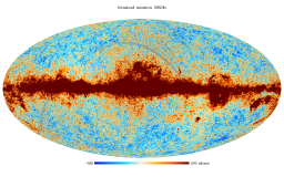
Nominal mission, 30 GHz
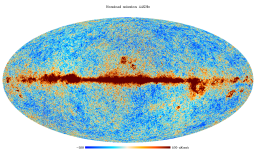
Nominal mission, 44 GHz
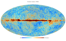
Nominal mission, 70 GHz
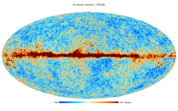
Nominal mission, 100 GHz
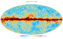
Nominal mission, 143 GHz
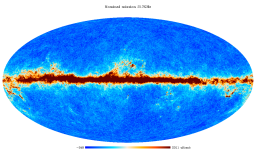
Nominal mission, 217 GHz
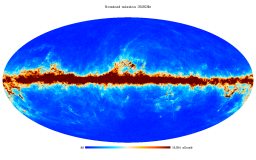
Nominal mission, 353 GHz
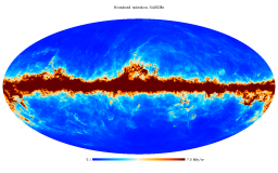
Nominal mission, 545 GHz
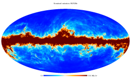
Nominal mission, 857 GHz


- Single survey maps
- Single survey maps are built using all valid detectors of a frequency channel; they cover separately the different sky surveys. The surveys are defined as the times over which the satellite spin axis rotates but 180 degrees, which, due to the position of the detectors in the focal plane does not cover the full sky, but a fraction between ~80 and 90% depending on detector position. During adjacent surveys the sky is scanned in opposite directions. More precisely it is the ecliptic equator that is scanned in opposite directions. While these are useful to investigate variable sources, they are also used to study the systematics of the time-response of the detectors as they scan bright sources, like the Galactic Plane, in different directions during different survey.
- Year maps
- These maps are built using the data of surveys 1+2, surveys 3+4, and so forth. They are used to study long-term systematic effects.
- half-mission maps
- for HFI, the half mission is defined after eliminating those rings discarded for all bolometers. There are 347 such rings, may of which are during the 5th survey when the End-of-Life tests were performed. The remaining 26419 rings are divided in half (up to the odd ring) to define the two halves of the mission. This exercise is done for the full mission only.
- Detector set or detector pairs maps
- The objective here is to split each frequency channel into two sets of detectors. For polarized channels four detectors (two PSB pairs for HFI) with different orientation on the sky are used, and the HFI SWBs are not included, while for the unpolarized channels the detectors are split into two pairs, where possible.
- Single detector maps
- These are built only for the HFI SWBs (non polarized) and contain only temperature data, of course.
| Frequency | DetSet1 | DetSet2 |
|---|---|---|
| 100 GHz | 100-1a/b & 100-4a/b | 100-2a/b & 100-3a/b |
| 143 GHz | 143-1a/b 1 & 43-3a/b | 143-2a/b & 143-4a/b |
| 217 GHz | 217-5a/b & 217-7a/b | 217-6a/b & 217-8a/b |
| 353 GHz | 353-3a/b & 353-5a/b | 353-4a/b & 353-6a/b |
| 545 GHz | 545-1 & 545-2 | 545-4 |
| 857 GHz | 857-1 & 857-2 | 857-3 & 857-4 |
- Half-ring maps
- Half-ring maps are built using only the first or the second half of the stable pointing period data. There are thus two half-ring maps per frequency channel named ringhalf_1 and ringhalf_2 respectively. These maps are built for characterization purposes in order to perform null tests. In particular, the difference between the two half-ring maps at a given frequency give a good estimate of the high frequency noise in the data (albeit biased low by ~0.5% for the HFI channels due to specifics of the TOI processing).
- Masks
- Masks are provided of the Galactic Plane and of the point sources. For the Galactic Plane, eight masks are given covering different fractions of the sky, and for the points sources two masks are given, at the 5 and 10 sigma level, for each Planck HFI frequency channel. These are generic masks, specific masks applicable to other products are delivered with the products themselves.
The table below gives the ranges in terms of ESA pointing-ID, HFI ring number, and OD. The OD ranges are indicative only: they indicate that the given ring occurs during that OD.
| Range | ODs | rings | pointing-IDs | Comment |
|---|---|---|---|---|
| nominal mission | 91 - 563 | 240 - 14723 | 00004200 - 03180200 | |
| full mission | 91 - 974 | 240 - 27005 | 00004200 - 05322620 | for HFI |
| Survey 1 | 91 - 270 | 240 - 5720 | 00004200 - 01059820 | |
| Survey 2 | 270 - 456 | 5721 - 11194 | 01059830 - 02114520 | |
| Survey 3 | 456 - 636 | 11195 - 16691 | 02114530 - 03193660 | |
| Survey 4 | 636 - 807 | 16692 - 21720 | 03193670 - 04243900 | |
| Survey 5 | 807 - 974 | 21721 - 27005 | 05267180 - 05322590 | end of mission for HFI |
| Survey 5 | 807 - 993 | 21721 - 27641 | 05267180 - 06344800 | end of survey for LFI |
| Survey 6 | 993 - tbd | 27642 - tbd | 06344810 - tbd | LFI only |
| HFI mission-half-1 | 91 - 531 | 240 - 13471 | 00004200 - 03155580 | |
| HFI mission-half-2 | 531 - 974 | 13472 - 27005 | 03155590 - 05322590 |
Caveats and known issues[edit]
The primary limitation of the HFI maps are TBW
The LFI 70 GHz maps at Nside=2048 should be considered as additional product, the default are the LFI maps at Nside=1024. No effective beam at Nside=2048 is provided, only at Nside=1024, for this reason the use of the effective beam with maps at Nside 2048 is discouraged.
Map zero-level[edit]
For the 100 to 857 GHz maps, the zero levels are set to their optimal levels for Galactic and CIB studies. A procedure for adjusting them to astrophysical values is given in the HFI Calibration paper Planck-2013-VIII[1].
For the 30, 44 and 70 GHz, maps are corrected for zero level monopole by applying an offset correction, see LFI Calibration paper Planck-2013-V[2] section 3.4 "Setting the zero levels in the maps". Note that the offset applied is indicated in the header as a comment keyword.
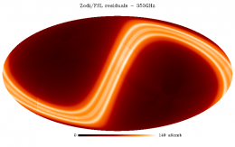
The Zodiacal light and the Far-Side Lobes[edit]
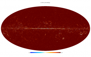
The figures below show the modeled Zodiacal light and Far Side Lobes projected onto the maps; they are simply the difference between the main product and the ZodiCorrected maps for the nominal mission. The units are given in the figures. The heat color table has been used in place of the standard Planck for clarity reasons.
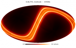
zodi/FSL rediduals - 100 GHz
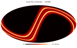
zodi/FSL rediduals - 143 GHz
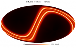
zodi/FSL rediduals - 217 GHz
zodi/FSL rediduals - 353 GHz
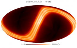
zodi/FSL rediduals - 545 GHz
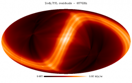
zodi/FSL rediduals - 857 GHz


The effects of the FSLs are seen most clearly at the highest frequencies, as structures roughly symmetric about the center of the image, which corresponds to the location of the Galactic Centre, which is in turn the source of most of the radiation that is scattered into the FSLs.
Artifacts near caustics of the scanning strategy[edit]
TBW, maybe
Production process[edit]
Sky maps are produced by combining appropriately the data of all working detectors in a frequency channel over some period of the mission. They give the best estimate of the signal from the sky (unpolarised) after removal, as far as possible, of known systematic effects and of the dipole signals induced by the motion of the solar system in the CMB and of the Planck satellite in the solar system. In particular, they include the Zodiacal light emission (Zodi for short) and also the scattering from the far-side lobes of the beams (FSL). More on this below.
HFI processing[edit]
The mapmaking and calibration process is described in detail in the Map-making section, where detailed references are found. In brief it consists of:
- binning the TOI data onto rings
- Healpix rings (HPRs) are used here, each ring containing the combined data of one pointing period.
- flux calibration
- at 100-353 GHz, the flux calibration factors are determined by correlating the signal with the orbital dipole, which is determined very accurately from the Planck satellite orbital parameters provided by Flight Dynamics. This provides a single gain factor per bolometer. At 545 and 857 GHz the gain is determined from the observation of Uranus and Neptune (but not Jupiter which is too bright) and comparison to recent models made explicitly for this mission. A single gain is applied to all rings at these frequencies.
- destriping
- in order to remove low-frequency noise, an offset per ring is determined by minimizing the differences between HPRs at their crossings, and removed.
- Zodiacal light correction
- a Zodiacal light model is used to build HPRs of the the Zodi emission, which is subtracted from the calibrated HPRs. (TBC)
- projection onto the map
- the offset-corrected, flux-calibrated, and Zodi-cleaned HPRs are projected onto Healpix maps, with the data of each bolometer weighted by a factor of 1/NET of that bolometer,
- Dust bandpass leakage correction
- the Q and U maps are corrected (REF)
- Fill missing pixels
- missing pixels are filled in with a value that is the mean of valid pixels within a given radius. A radius of 1 deg is used for the full channel maps, and 1.5 deg is used for the detset maps.
- Far Side Lobe calibration correction
- the 100-217 maps are multiplied by factors of 1.00087, 1.00046, and 1.00043, respectively, to compensate for the non-removal of the far-side lobes.
These maps provide the main mission products. Together with signal maps, hit count, variance, and variance maps are also produced. The hit maps give the (integer) number of valid TOI-level samples that contribute to the signal of each pixel. All valid samples are counted in the same way, i.e., there is no weighting factor applied. The variance maps project the white noise estimate, provided by the NETs, in the sky domain.
LFI processing[edit]
LFI maps were constructed with the Madam map-making code, version 3.7.4. The code is based on generalized destriping technique, where the correlated noise component is modeled as a sequence of constant offset, called baselines. A noise filter was used to constrain the baseline solution allowing the use of 1 second baselines.
Radiometers were combined according to the horn-uniform weighting scheme to minimize systematics. The used weights are listed in Map-making. The flagged samples were excluded from the analysis by setting their weights to $C_{w}^{-1}$ = 0. The galaxy region was masked out in the destriping phase, to reduce error arising from strong signal gradients. The polarization component was included in the analysis, although only the temperature maps are released.
A detailed description of the map-making procedure is given in Planck-2013-II[3] and in section Map-making.
Inputs[edit]
HFI inputs[edit]
- The cleaned TOIs of signal of each detector, together with their flags, produced by the TOI processing pipeline
- The TOIs of pointing (quaternions), described in Detector pointing
- Bolometer-level characterization data, from the DPC's internal IMO (not distributed)
- Planck orbit data used to compute and remove the earth dipole
- WMAP solar dipole information used to calibrate the CMB channels
- Planet models used to calibrate the Galactic channels.
LFI inputs[edit]
The Madam map-maker takes as an input:
- The calibrated timelines (for details see TOI Processing)
- The detector pointings (for details see Detector pointing)
- The noise information in the form of three-parameter (white noise level ($\sigma$), slope, and knee frequency ($f_\mathrm{knee}$)) noise model (for details see RIMO)
Related products[edit]
Masks[edit]
Masks are provided of
- the point sources
- 15 masks are provided, three for the LFI (one mask for each frequency masking at the 4 level) and 12 for the HFI (two masks for each frequency at the 5 and 10 levels. For the HFI the masks can be used as they are, for the LFI they need to be downgraded to Nside=1024 except for the 70 GHz channel at Nside=2048 which does not need to be downgraded.
- the Galactic Plane
- 8 masks are provided giving 20, 40, 60, 70, 80, 90, 97, and 99% sky coverage in two different files, at Nside=2048. For the HFI they can be used as they are, for the LFI they need to be downgraded at Nside=1024 (note that if using the 70 GHZ at Nside=2048 no downgraded is needed)
The masks are binary, in GALACTIC coordinates, and NESTED ordering. The table below give the filenames.
| Frequency | LFI Point Source masks |
|---|---|
| 30GHz | LFI_MASK_030-ps_2048_R1.00.fits |
| 44GHz | LFI_MASK_044-ps_2048_R1.00.fits |
| 70GHz | LFI_MASK_070-ps_2048_R1.00.fits |
| HFI Point Source masks | |
| HFI_Mask_PointSrc_2048_R1.10.fits | |
| Galactic Plane masks | |
| HFI_Mask_GalPlane_2048_R1.10.fits | |
The masks are shows below in a single figure. While this is quite clear for the Galactic Plane masks, it is less so for the point source masks, but it does give a clear perspective on how the latter are distributed over the sky.
Galactic Plane masks
PointSource masks


File names[edit]
The FITS filenames are of the form {H|L}FI_SkyMap_fff_nnnn_R1.nn_{coverage}_{type}.fits, where fff are three digits to indicate the Planck frequency band, and nnnn is the Healpix Nside of the map, coverage indicates which part of the mission is covered, and the optional type indicates the subset of input data used. A full list of products, with links to them in the Archive, is given in the tables below.
For the benefit of users who are only looking for the frequency maps with no additional information, we also provide a file combining the 9 frequency maps as separate columns in a single extension. The 9 columns in this file contain the intensity maps ONLY and no other information (hit maps and variance maps) is provided.
| Frequency | Full channel maps |
|---|---|
| 30GHz | LFI_SkyMap_030_1024_R1.10_nominal.fits |
| 44GHz | LFI_SkyMap_044_1024_R1.10_nominal.fits |
| 70GHz | LFI_SkyMap_070_1024_R1.10_nominal.fits |
| 70GHz | LFI_SkyMap_070_2048_R1.10_nominal.fits |
| 100GHz | HFI_SkyMap_100_2048_R1.10_nominal.fits |
| 143GHz | HFI_SkyMap_143_2048_R1.10_nominal.fits |
| 217GHz | HFI_SkyMap_217_2048_R1.10_nominal.fits |
| 353GHz | HFI_SkyMap_353_2048_R1.10_nominal.fits |
| 545GHz | HFI_SkyMap_545_2048_R1.10_nominal.fits |
| 857GHz | HFI_SkyMap_857_2048_R1.10_nominal.fits |
| Frequency | Full channel, Zodi-corrected maps |
| 100GHz | HFI_SkyMap_100_2048_R1.10_nominal_ZodiCorrected.fits |
| 143GHz | HFI_SkyMap_143_2048_R1.10_nominal_ZodiCorrected.fits |
| 217GHz | HFI_SkyMap_217_2048_R1.10_nominal_ZodiCorrected.fits |
| 353GHz | HFI_SkyMap_353_2048_R1.10_nominal_ZodiCorrected.fits |
| 545GHz | HFI_SkyMap_545_2048_R1.10_nominal_ZodiCorrected.fits |
| 857GHz | HFI_SkyMap_857_2048_R1.10_nominal_ZodiCorrected.fits |
| Frequency | Combined frequency maps |
| All | COM_MapSet_I-allFreqs_R1.10_nominal.fits |
FITS file structure[edit]

The FITS files for the sky maps contain a minimal primary header with no data, and a BINTABLE extension (EXTENSION 1, EXTNAME = FREQ-MAP) containing the data. The structure is shows schematically in the figure at right.
The FREQ-MAP extension contains is a 3-column table that contain the signal, hit-count and variance maps, all in Healpix format, in columns 1, 2, and 3, respectively. The number of rows is 50331648 for HFI and LFI 70 GHz at Nside=2048 and 12582912 for LFI maps at Nside=1024 (N.B: Npix = 12 Nside^2). The three columns are I_STOKES for the intensity (or temperature) signal, HIT for the hit-count and II_COV for the variance. The exact order of the columns in the figure is indicative only, and the details can be found in the keywords.
Keywords indicate the coordinate system (GALACTIC), the Healpix ordering scheme (NESTED), the units (K_cmb or MJy/sr) of each column, and of course the frequency channel (FREQ). The COMMENT fields give a one-line summary of the product, and some other information useful for traceability within the DPCs. The original filename is also given in the FILENAME keyword as are the datasum and the md5 checksum for the extension. The BAD_DATA keyword gives the value used by Healpix to indicate pixels for which no signal is present (these will also have a hit-count value of 0). The COMMENT fields give further information including some traceability data for the DPC's. The main parameters are summarised below:
| 1. EXTNAME = 'FREQ-MAP' : Data columns | |||
|---|---|---|---|
| Column Name | Data Type | Units | Description |
| I_STOKES | Real*4 | K_cmb or MJy/sr | The signal map |
| HITS | Int*4 | none | The hit-count map |
| II_COV | Real*4 | K_cmb2 or (MJy/sr)2 | The variance map |
| Keyword | Data Type | Value | Description |
| PIXTYPE | string | HEALPIX | |
| COORDSYS | string | GALACTIC | Coordinate system |
| ORDERING | string | NESTED | Healpix ordering |
| NSIDE | Int | 1024 or 2048 | Healpix Nside |
| FIRSTPIX | Int*4 | 0 | First pixel number |
| LASTPIX | Int*4 | 12582911 or 50331647 | Last pixel number |
| FREQ | string | nnn | The frequency channel |
The same structure applies to all SkyMap products, independent of whether they are full channel, survey of half-ring. The distinction between the types of maps is present in the FITS filename (and in the traceability comment fields).
References[edit]
- ↑ Planck 2013 results. VIII. HFI photometric calibration and Map-making, Planck Collaboration, 2014, A&A, 571, A8
- ↑ Planck 2013 results. V. LFI Calibration, Planck Collaboration, 2014, A&A, 571, A5
- ↑ Planck 2013 results. II. Low Frequency Instrument data processing, Planck Collaboration, 2014, A&A, 571, A2
To be defined / determined
(Planck) High Frequency Instrument
Flexible Image Transfer Specification
random telegraphic signal
Cosmic Microwave background
European Space Agency
Operation Day definition is geometric visibility driven as it runs from the start of a DTCP (satellite Acquisition Of Signal) to the start of the next DTCP. Given the different ground stations and spacecraft will takes which station for how long, the OD duration varies but it is basically once a day.
(Planck) Low Frequency Instrument
[LFI meaning]: absolute calibration refers to the 0th order calibration for each channel, 1 single number, while the relative calibration refers to the component of the calibration that varies pointing period by pointing period.
To be confirmed
Noise Equivalent Temperature
Data Processing Center