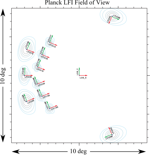
Beams LFI
Contents
Wish List[edit]
list of information to be inserted in the explanatory supplements
- Description of LFI FOV.
- Description of various telescope models as reported in the beam paper.
- Format of beam data
- Definition of various coordinate frames for beams
Overview[edit]
LFI is observing the sky with 11 pairs of beams associated with the 22 pseudo-correlation radiometers. Each beam of the radiometer pair (Radiometer Chain Assembly - RCA) is named as LFIXXM or LFIXXS. XX is the RCA number ranging from 18 to 28; M and S are the two polarization namely main-arm and side-arm of the Orthomode transduccers #darcangelo2009b.

Main Beams and Focal Plane calibration[edit]
As the focal plane calibration we refer to the determination of the beam pointing parameters in the nominal Line of Sight (LOS) frame through main beam measurments using Jupiter transits. the parametes that characterise the beam pointing are the following:
Effective beams[edit]
TBW
Window Functions[edit]
TBW
Sidelobes[edit]
TBW
References[edit]
<biblio force=false>
</biblio>
(Planck) Low Frequency Instrument
Field-Of-View
LFI Radiometer Chain Assembly
[LFI meaning]: absolute calibration refers to the 0th order calibration for each channel, 1 single number, while the relative calibration refers to the component of the calibration that varies pointing period by pointing period.
Line Of Sight