Pre-processing
Contents
Overview[edit]
In terms of data processing, the HFI ground segment handles two types of data, both made available via the MOC:
- telemetry data transmitted from the satellite. These come from the different subsystems of the satellite service module, from the sorption cooler and from the two instruments.
- auxiliary data. These are data produced by MOC. The only 3 products used by the HFI DPC are the pointing data, the orbit data, and the time correlation data.
All data are retrieved by the HFI level 1 software and stored in the HFI database.
Telemetry data[edit]
The digitized data from the satellite are assembled on board in packets according to the ESA Packet Telemetry Standard and Packet Telecommand Standard, the CCSDS Packet Telemetry recommendations and the ESA Packet Utilization Standard. The packets are dumped to the ground during the Daily Tranmission Control Period, consolidated by and stored at MOC. Telemetry data contain the housekeeping data and the bolometer (ie science) data.
Housekeeping data[edit]
For several reasons (systems monitoring, potential impact of the environment, understanding of the bolometer data), the HFI level 1 software gathers and stores in its database the satellite subsystems housekeeping parameters:
- Command and Data Management System
- Attitude Control & Measurement Subsystem
- Thermal Control System
- Sorption Cooler System
- HFI housekeeping parameters
The structure and the frequency of the packets built by these subsystems and the format of the house keeping parameters are described in the Mission Information Bases. The HFI L1 software uses these MIBs to extract the house keeping parameters from the packets. Given the status of each subsystem, the parameters are gathered in the HFI database in groups. The HFI L1 software builds in each group a vector of time (usually named TIMESEC) and a single vector per housekeeping parameter.
Bolometer data[edit]
The HFI science data is retrieved and reconstructed as described in section 3.1 of Planck-Early-VI[1].
The first stage of HFI data processing is performed on-board in order to generate the telemetry. This is described in the data compression section.
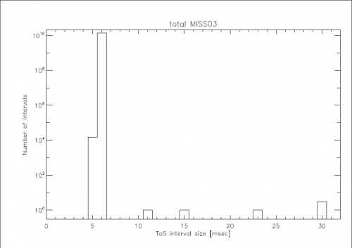
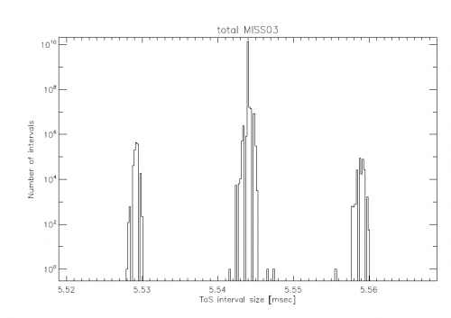
On board, the signal from the 72 HFI channels is sampled at 180.4Hz by the Read-out Electronic Unit. 254 samples per channel are grouped into a compression slice. The Data Processing Unit then builds a set of several telemetry packets containing the compression slice data and adds to the first packet the start time of the compression slice. When receiving this set of telemetry packets, the L1 software extracts the samples and computes the time of each sample based on the compression slice start time (digitized with μs quantization steps) and a mean sample time between samples. For the nominal instrument configuration, the sample integration time is measured to be Tsamp = 5.54404 ms
The two plots show the histogram of time differences between two successive samples for the full mission. 6 sample intervals (> 6 ms) correspond to 3 occurrences of packets lost on board when the on board sofwtare of the Command and Data Management Unit has been patched (18, 19 and 20th of August 2009). The right plot is a blow up of the left one. It shows the distribution around the mean value of 5,54 ms and the 15 μs quantization step.
Transfer functions[edit]
In order to ease the reading data in the HFI database, so called transfer functions are created. They allow software items to read data on which functions are applied on the fly. A simple example of a transfer function is the conversion of a thermometer data in Analogic to Digital Units (ADU) to Kelvins. Here we show the 2 transfer functions applied on the bolometer samples in the data processing pipelines:
From raw signal to non demodulated signal in Volts (transf1_nodemod)
where:
- refers to a bolometer usually labelled by its electronic belt and channel. Eg. bc=00 refers to the a part of the first 100 GHz Polarized Sentivite Bolometer.
- is the bolometer sample in Analogic Digital Units (ADU)
- is the number of samples in half a modulation period. This parameter is common to all bolometer channels and - although kept fixed during the whole mission - is read from the housekeeping parameter.
- is the number of samples suppressed at the beginning oft each half modulation period. Although kept fixed during the whole mission, it is read from the housekeeping parameter. For bc=00,
- is a calibration factor. For bc=00, .
- is close to 32768
- is the gain amplifier mesured during the calibration phase. For bc=00,
- is the current gain amplifier. Although kept fixed during the whole mission, it is read from the housekeeping parameter. For bc=00,
From raw signal to demodulated signal in Volts (transf1)
The same formula as above is used but with the demodulation and a 3-point filter computed as:
where:
- , and refer to the samples before and after the given sample to demodulate
- is computed by the HFI L1 software
Statistics on the telemetry data[edit]
The table gives some statistics about the data handled at the pre-processing level:
| Nominal mission(1) | Full mission(1) | From launch to the end of full mission(1) | |
|---|---|---|---|
| Duration | days | days | days |
| Number of HFI packets generated onboard (HSK/science)(2) | / | / | / |
| Number of HFI packets lost (3) (HSK/science) | / | / | / |
| Ratio of HFI lost packets vs generated on board (HSK/science) | / | / | / |
| Number of different housekeeping parameters stored in the database (HFI/SCS/sat) | / / | ||
| Number of science samples stored in the database | |||
| Number of missing science samples | (4) | ||
| Ratio of missing science samples vs samples stored | |||
- (1) : mission periods are defined in this page.
- (2) : science packets refer to the number of telemetry packets containing science data (ie: bolometer data and fine thermometer data) when the instrument is in observation mode (Application Program IDentifier = 1412). HSK packets refer to the number of HFI non essential housekeeping telemetry packets (Application Program IDentifier = 1410).
- (3) : all lost packets have been lost on board ; no HFI packet has been lost at ground segment level.
- (4) : this amount of lost science samples is distributed as
- 0.3% are due to Single Event Unit
- 18.5% have been lost during the 3 CDMU patch days and the consecutive clock resynchronisation
- 29.1% have been lost because of compression errors
- 52.1% have been lost due to the EndOfSlew buffer overflow being triggered by solar flare events
Pointing data[edit]
The pointing data are built by the MOC Flight Dynamics team. The pointing data are made available to the DPC via AHF files. See AHF description document and AHF files repository. All data contained in the AHF files are ingested in the HFI database. The present section describes the steps to produce the HFI pointing solution.
- During the stable pointing period (ie during the dwell), data sampling rate is given at 8 Hz while it is at 4 Hz during the satellite slews. Those data are thus interpolated to the bolometer sampling rate using a spherical linear interpolation as described in section 3.4 of of Planck early paper VI .
- The pointing solution is then amended from the wobble effect as delivered by MOC Flight Dynamics in the AHF files.
- A final correction is then applied based on the study of main planets and point sources seen by the bolometers.
Note: an
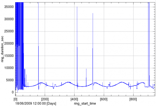
HFI ring corresponds to each stable pointing period, when the spin axis is pointing towards an essentially fixed direction in the sky and the detectors repeatedly scan the same circle on the sky. More precisely the HFI ring start time is defined as the time of the first thurster firing. The end time of the HFI ring is the start time of the following ring.
The plot below shows the evolution of the ring duration along the whole mission. It mainly reflects the scanning strategy and few long rings due to operational constraints or tests.
Orbit data[edit]
Satellite orbit velocity is built by the MOC Flight Dynamics team and made available to the HFI DPC via orbit files. See Orbit description document and
orbit files repository.
As those orbit files contain both effective and predictive data, they are regularly ingested updated in the HFI database.
Note: these same data are also ingested in parallel into the JPL Horizons system under ESA’s responsibility.
The satellite orbit data preprocessing is the following.
- The sampling of the MOC provided orbit velocity data is appromximately 1 every 5 mn. These data are interpolated to the time of the middle of the HFI rings.
- The reference frame of the orbit data is translated from the MOC given Earth Mean Equator and Equinox J2000 (EME2000) reference frame to the ecliptic reference frame in cartesian coordinates.
- The earth velocity provided by the NASA JPL Horizons system is interpolated to the time of the middle of the HFI rings. It is then added to the satellite velocity data.
The use of the satellite orbit velocity is three-fold:
- computation of the CMB orbital dipole (see calibration section),
- computation of the positions of solar system objects (see data masking section),
- computation of the abberation correction.
Time correlation data[edit]
The MOC is responsible for providing information about the relationship between the satellite On Board Time (OBT) and Coordinated Universal Time (UTC). This information comes via several measurements of OBT and UTC pairs each day, measured during the satellite ranging. See Time Correlation document.
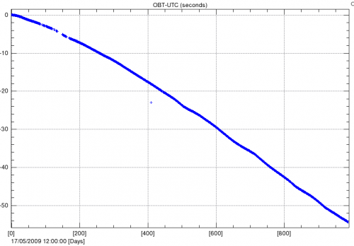
The following plot shows the (OBT, UTC) data couples provided by MOC since Planck launch. The x axis is in number of days since the 17th of May 2009 while the y axis is the difference of OBT and UTC in seconds. The very slow drift is approximately 0.05 seconds per day. The small wiggles are due to the satellite global temperature trends due to its orbit and distance to the sun.
Note: The isolated point on the 1st of June 2010 (just above 400 in abscisse) is not significant and due to a misconfiguration of the ground station parameters.
An order 3 polynomial is then fitted to the data. As the whole HFI data management and processing uses OBT, the OBT-UTC information is only used when importing orbit data from Horizons.
References[edit]
- ↑ Planck early results. VI. The High Frequency Instrument data processing, Planck HFI Core Team, A&A, 536, A6, (2011).
(Planck) High Frequency Instrument
[ESA's] Mission Operation Center [Darmstadt, Germany]
Data Processing Center
European Space Agency
House-Keeping data
Sorption Cooler Subsystem (Planck)
Command and Data Management Unit
Attitude History File
Cosmic Microwave background
On-Board Time
Universal Time Coordinate(d)


