Difference between revisions of "LFI overview"
| Line 1: | Line 1: | ||
| + | {{DISPLAYTITLE:LFI design, qualification and performance}} | ||
The Planck-LFI instrument is an array of 11 radiometric receivers in the Ka, Q and V bands, with centre frequencies close to 30, 44 and 70 GHz. The exact centre frequencies for each receiver are reported in <cite>#planck2011-1-4</cite> {{PEarly|3}}; for simplicity, here we will refer to the three channels using their nominal centre frequency. A detailed description of the LFI instrument is given in <cite>#bersanelli2010</cite> {{PPreLaunch|4}}, and references therein. | The Planck-LFI instrument is an array of 11 radiometric receivers in the Ka, Q and V bands, with centre frequencies close to 30, 44 and 70 GHz. The exact centre frequencies for each receiver are reported in <cite>#planck2011-1-4</cite> {{PEarly|3}}; for simplicity, here we will refer to the three channels using their nominal centre frequency. A detailed description of the LFI instrument is given in <cite>#bersanelli2010</cite> {{PPreLaunch|4}}, and references therein. | ||
Revision as of 18:58, 17 March 2013
The Planck-LFI instrument is an array of 11 radiometric receivers in the Ka, Q and V bands, with centre frequencies close to 30, 44 and 70 GHz. The exact centre frequencies for each receiver are reported in #planck2011-1-4 Planck early paper III ; for simplicity, here we will refer to the three channels using their nominal centre frequency. A detailed description of the LFI instrument is given in #bersanelli2010 Planck pre-launch paper 4, and references therein.
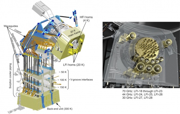
The heart of the LFI instrument is a compact, multi-frequency array of differential receivers with ultra-low-noise amplifiers based on cryogenic indium phosphide (InP) high-electron-mobility transistors (HEMTs). To minimise power dissipation in the focal plane unit, which is cooled to 20 K, the radiometers are split into two subassemblies connected by a set of waveguides, as shown in Fig. 1, left panel.
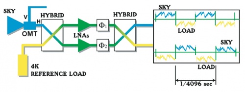
The LFI horns are situated in a ring around the HFI, see Fig. 1 – right panel. Each horn collects radiation from the telescope and feeds it to one or more detectors. The radiometer design is driven by the need to suppress 1/f-type noise induced by gain and noise temperature fluctuations in the amplifiers, which would be unacceptably high for a simple total power system. A differential pseudo-correlation scheme is adopted, in which signals from the sky and from a black-body reference load are combined by a hybrid coupler, amplified in two independent amplifier chains, and separated out by a second hybrid (Fig. 2). The sky and the reference load power can then be measured and differenced. Since the reference signal has been subject to the same gain variations in the two amplifier chains as the sky signal, the true sky power can be recovered. Insensitivity to fluctuations in the back-end amplifiers and detectors is realized by switching phase shifters at ∼8 kHz synchronously in each amplifier chain. The rejection of 1/f noise as well as the immunity to other systematic effects is optimised if the two input signals are nearly equal. For this reason the reference loads are cooled to ∼4 K by mounting them on the 4-K structure of the HFI. In addition, the effect of the residual offset (< 2 K in nominal conditions) is reduced by introducing a gain modulation factor in the on-board processing to balance the output signal #Seiffert2002. The differencing receiver greatly improves the stability of the measured signal.

References[edit]
<biblio force=false>
</biblio>
(Planck) Low Frequency Instrument
(Planck) High Frequency Instrument
