Difference between revisions of "Beams LFI"
(→Overview) |
(→Overview) |
||
| Line 16: | Line 16: | ||
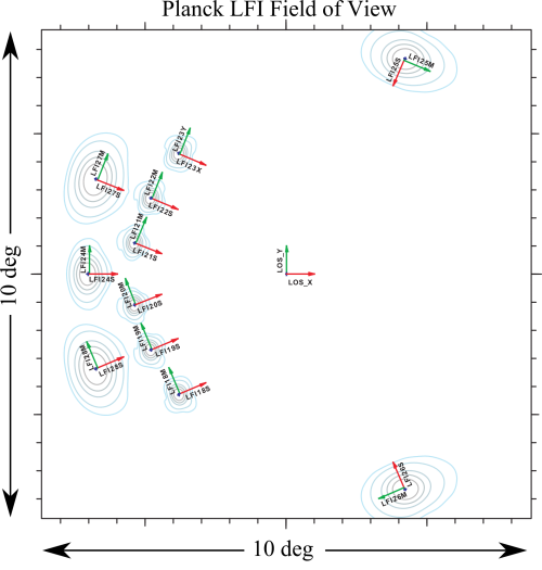
| + | [[File:fieldofview.png|500px|thumb|centre|Figure 1.]] | ||
| − | |||
| − | |||
| − | |||
| − | |||
| − | |||
The separation of the power pattern into a main beam and sidelobes can be somewhat arbitrary and is basically governed by convention. Different definitions of these regions could in principle be used: electromagnetic definitions, science-related definitions, and simulation-related definitions. In this framework the main beam region was defined by taking care that not only the relevant main beam characteristics are computed (angular resolution, ellipticity, directivity, cross polar discrimination factor, and so on), but also that the main beam distortion, at a level of about –60 dB (mainly due to the off-axis location of the LFI feed horns), can be evaluated. | The separation of the power pattern into a main beam and sidelobes can be somewhat arbitrary and is basically governed by convention. Different definitions of these regions could in principle be used: electromagnetic definitions, science-related definitions, and simulation-related definitions. In this framework the main beam region was defined by taking care that not only the relevant main beam characteristics are computed (angular resolution, ellipticity, directivity, cross polar discrimination factor, and so on), but also that the main beam distortion, at a level of about –60 dB (mainly due to the off-axis location of the LFI feed horns), can be evaluated. | ||
Revision as of 13:47, 25 February 2013
Contents
Wish List[edit]
list of information to be inserted in the explanatory supplements
- Description of LFI FOV.
- Description of various telescope models as reported in the beam paper.
- Format of beam data
- Definition of various coordinate frames for beams
Overview[edit]
LFI is observing the sky with 11 pairs of beams associated with the 22 pseudo-correlation radiometers. Each beam of the radiometer pair (Radiometer Chain Assembly - RCA) is named as LFIXXM or LFIXXS. XX is the RCA number ranging from 18 to 28; M and S are the two polarization namely main-arm and side-arm of the Orthomode transduccers #darcangelo2009b.
The separation of the power pattern into a main beam and sidelobes can be somewhat arbitrary and is basically governed by convention. Different definitions of these regions could in principle be used: electromagnetic definitions, science-related definitions, and simulation-related definitions. In this framework the main beam region was defined by taking care that not only the relevant main beam characteristics are computed (angular resolution, ellipticity, directivity, cross polar discrimination factor, and so on), but also that the main beam distortion, at a level of about –60 dB (mainly due to the off-axis location of the LFI feed horns), can be evaluated.
Main Beams and Focal Plane calibration[edit]
Describe the RIMO content (beam section)
The beam solid angle, Ω, of an antenna is given by
\Omega where is the normalized power pattern and the field computed by GRASP is normalised to a total power of 4π watt, i.e.,
Effective beams[edit]
TBW
Window Functions[edit]
TBW
Sidelobes[edit]
TBW
References[edit]
<biblio force=false>
</biblio>
(Planck) Low Frequency Instrument
Field-Of-View
LFI Radiometer Chain Assembly
[LFI meaning]: absolute calibration refers to the 0th order calibration for each channel, 1 single number, while the relative calibration refers to the component of the calibration that varies pointing period by pointing period.
