Difference between revisions of "LFI systematic effect uncertainties"
| Line 145: | Line 145: | ||
<!-- | <!-- | ||
| + | |||
==Effects independent of sky signal== | ==Effects independent of sky signal== | ||
===Noise correlations and 1/f noise=== | ===Noise correlations and 1/f noise=== | ||
TBW | TBW | ||
| − | + | ||
As described in {{BibCite|seiffert2002}}{{PlanckPapers|planck2011-1-4}} imperfect matching of components generates isolation between the complementary diodes of a receiver between −10 and −15 dB. This imperfect isolation leads to a small anti correlated component in the white noise that is cancelled by a weighted average of the time ordered data from the two diodes of each receiver as the first step of analysis. This avoids the complication of tracking the anti correlated white noise throughout the analysis. | As described in {{BibCite|seiffert2002}}{{PlanckPapers|planck2011-1-4}} imperfect matching of components generates isolation between the complementary diodes of a receiver between −10 and −15 dB. This imperfect isolation leads to a small anti correlated component in the white noise that is cancelled by a weighted average of the time ordered data from the two diodes of each receiver as the first step of analysis. This avoids the complication of tracking the anti correlated white noise throughout the analysis. | ||
We treat the combined diode data as the raw data, and calibration, noise estimation, map making etc. are performed on these combined data. The weights were determined from some initial estimates of the calibrated noise for each detector, and are kept fixed for the entire mission. | We treat the combined diode data as the raw data, and calibration, noise estimation, map making etc. are performed on these combined data. The weights were determined from some initial estimates of the calibrated noise for each detector, and are kept fixed for the entire mission. | ||
| Line 156: | Line 157: | ||
Over the course of the nominal mission, the noise is well fit by the model, with the exception of the early parts of sky survey 3. During this time, thermal instabilities brought on by the switchover from the nominal to the redundant sorption cooler cause poor fits and some changes in the parameters. | Over the course of the nominal mission, the noise is well fit by the model, with the exception of the early parts of sky survey 3. During this time, thermal instabilities brought on by the switchover from the nominal to the redundant sorption cooler cause poor fits and some changes in the parameters. | ||
| − | + | ||
===Thermal effects=== | ===Thermal effects=== | ||
TBW | TBW | ||
| − | + | ||
The LFI is susceptible to temperature fluctuations in the 300 K back-end modules, in the 4 K reference loads and in the 20 K focal plane. | The LFI is susceptible to temperature fluctuations in the 300 K back-end modules, in the 4 K reference loads and in the 20 K focal plane. | ||
| Line 173: | Line 174: | ||
Details about the thermal stability performance of Planck can be found in {{PlanckPapers|planck2011-1-3}}, while the susceptibility of the LFI to temperature variations is discussed in {{BibCite|terenzi2009b}}. | Details about the thermal stability performance of Planck can be found in {{PlanckPapers|planck2011-1-3}}, while the susceptibility of the LFI to temperature variations is discussed in {{BibCite|terenzi2009b}}. | ||
| − | + | ||
===Bias fluctuations=== | ===Bias fluctuations=== | ||
| Line 179: | Line 180: | ||
TBW | TBW | ||
| − | + | ||
The signal detected by the radiometers can vary because of fluctuations in the front-end and back-end amplifiers bias voltages. In the LFI these fluctuations occurred according to two time scales: | The signal detected by the radiometers can vary because of fluctuations in the front-end and back-end amplifiers bias voltages. In the LFI these fluctuations occurred according to two time scales: | ||
| Line 187: | Line 188: | ||
The effect of slow drifts is suppressed by the pseudo-correlation architecture of the differential radiometers. Fast electric changes produce quasi-random fluctuations and abrupt steep drops or jumps in the signal. If jumps are caused by instabilities in the front-end bias voltage then the effect involves the output voltage of both diodes in the radiometer. When the jumps occur in the back-end detector diodes (so-called “pop-corn noise”) they impact only the output voltage of the corresponding diode and affect sky and reference load samples. In both cases the differenced signal is largely immune from these effects. | The effect of slow drifts is suppressed by the pseudo-correlation architecture of the differential radiometers. Fast electric changes produce quasi-random fluctuations and abrupt steep drops or jumps in the signal. If jumps are caused by instabilities in the front-end bias voltage then the effect involves the output voltage of both diodes in the radiometer. When the jumps occur in the back-end detector diodes (so-called “pop-corn noise”) they impact only the output voltage of the corresponding diode and affect sky and reference load samples. In both cases the differenced signal is largely immune from these effects. | ||
| − | |||
===1-Hz spikes=== | ===1-Hz spikes=== | ||
| Line 193: | Line 193: | ||
TBW | TBW | ||
| − | + | ||
This effect is caused by pickup from the housekeeping electronics clock that occurs after the detector diodes and before the ADC converters {{PlanckPapers|planck2011-1-4}}{{BibCite|meinhold2009}}{{PlanckPapers|mennella2010}}. This spurious signal is detected in the radiometer time-domain outputs as a one second square wave with a rising edge near 0.5 s and a falling edge near 0.75 s in on-board time. In the frequency domain it appears at multiples of 1 Hz. | This effect is caused by pickup from the housekeeping electronics clock that occurs after the detector diodes and before the ADC converters {{PlanckPapers|planck2011-1-4}}{{BibCite|meinhold2009}}{{PlanckPapers|mennella2010}}. This spurious signal is detected in the radiometer time-domain outputs as a one second square wave with a rising edge near 0.5 s and a falling edge near 0.75 s in on-board time. In the frequency domain it appears at multiples of 1 Hz. | ||
Frequency spikes are present at some level in the output from all detectors, but affect the 44 GHz data most strongly because of the low voltage output and high post-detection gain values in that channel. For this reason spikes are removed from the 44 GHz time-ordered data via template fitting, as described in {{PlanckPapers|planck2013-p02}}. | Frequency spikes are present at some level in the output from all detectors, but affect the 44 GHz data most strongly because of the low voltage output and high post-detection gain values in that channel. For this reason spikes are removed from the 44 GHz time-ordered data via template fitting, as described in {{PlanckPapers|planck2013-p02}}. | ||
| − | + | ||
===Main Beam Ellipticity=== | ===Main Beam Ellipticity=== | ||
| Line 211: | Line 211: | ||
TBW | TBW | ||
| − | + | ||
Straylight contamination arise from the spurious signal pickup from the telescope far sidelobes. Main sources of straylight contamination are the Galaxy, especially at 30 GHz, and the cosmological dipole, mainly detected in the directions of the main and sub reflectors spillover. In principle we should also include the straylight contribution from the orbital dipole, but its effect is of a factor ten lower than the cosmic dipole so that it can safely be neglected in this framework (but it has been considered in the calibration pipeline). Further details about the Planck optical system are reported in {{PlanckPapers|tauber2010b}} and the LFI beam properties are provided in {{PlanckPapers|sandri2010}}. | Straylight contamination arise from the spurious signal pickup from the telescope far sidelobes. Main sources of straylight contamination are the Galaxy, especially at 30 GHz, and the cosmological dipole, mainly detected in the directions of the main and sub reflectors spillover. In principle we should also include the straylight contribution from the orbital dipole, but its effect is of a factor ten lower than the cosmic dipole so that it can safely be neglected in this framework (but it has been considered in the calibration pipeline). Further details about the Planck optical system are reported in {{PlanckPapers|tauber2010b}} and the LFI beam properties are provided in {{PlanckPapers|sandri2010}}. | ||
| Line 218: | Line 218: | ||
Because of the beam orientation, the straylight fingerprint is different in odd surveys compared to even surveys. The Galaxy, for example, is detected by the sub spillover in the odd surveys and by the main spillover in the even surveys. Because the sub spillover points approximately in the main beam direction, the Galaxy straylight pattern is close to the galactic plane. The main spillover, instead, points at about 85 degrees from the main beam so that the Galaxy is re-imaged onto a ring. | Because of the beam orientation, the straylight fingerprint is different in odd surveys compared to even surveys. The Galaxy, for example, is detected by the sub spillover in the odd surveys and by the main spillover in the even surveys. Because the sub spillover points approximately in the main beam direction, the Galaxy straylight pattern is close to the galactic plane. The main spillover, instead, points at about 85 degrees from the main beam so that the Galaxy is re-imaged onto a ring. | ||
| − | + | ||
===ADC non linearity=== | ===ADC non linearity=== | ||
| Line 224: | Line 224: | ||
TBW | TBW | ||
| − | + | ||
The linearity of analogue-to-digital converters (ADC) requires that the voltage step sizes between successive binary outputs are | The linearity of analogue-to-digital converters (ADC) requires that the voltage step sizes between successive binary outputs are | ||
| Line 232: | Line 232: | ||
The typical amplitude of the region where the non linearity occurs is of the order of 1 mV, corresponding to about three bits in the ADC. The ADC effect is strongest (3 to 6%) in the 44 GHz channels, because of their lower detector voltages. The ADC non linearity effect has been characterised from flight data and removed from the TOIs according to the procedure described in the main LFI data processing paper {{PlanckPapers|planck2013-p02}}. | The typical amplitude of the region where the non linearity occurs is of the order of 1 mV, corresponding to about three bits in the ADC. The ADC effect is strongest (3 to 6%) in the 44 GHz channels, because of their lower detector voltages. The ADC non linearity effect has been characterised from flight data and removed from the TOIs according to the procedure described in the main LFI data processing paper {{PlanckPapers|planck2013-p02}}. | ||
| − | + | ||
===Imperfect photometric calibration=== | ===Imperfect photometric calibration=== | ||
| − | + | ||
An important set of systematic effects are those related with the photometric calibration of the radiometers. Such effects are discussed at length by {{PlanckPapers|planck2013-p05}}. There are three different kinds of systematic effects that can affect the calibration. | An important set of systematic effects are those related with the photometric calibration of the radiometers. Such effects are discussed at length by {{PlanckPapers|planck2013-p05}}. There are three different kinds of systematic effects that can affect the calibration. | ||
| Line 244: | Line 244: | ||
* Incorrect reconstruction of gain fluctuations. Some of the algorithms we used in calibrating LFI data for this release use the radiometer equation and the recorded variations of the radiometers total-power output to track gain changes. In principle, any deviation in the behaviour of the radiometer from the ideal case (e.g., ADC non linearities) can therefore induce systematic effects in the gain curves. | * Incorrect reconstruction of gain fluctuations. Some of the algorithms we used in calibrating LFI data for this release use the radiometer equation and the recorded variations of the radiometers total-power output to track gain changes. In principle, any deviation in the behaviour of the radiometer from the ideal case (e.g., ADC non linearities) can therefore induce systematic effects in the gain curves. | ||
| − | + | ||
===Pointing effects=== | ===Pointing effects=== | ||
| Line 250: | Line 250: | ||
TBW | TBW | ||
| − | + | ||
Pointing uncertainties are translated into uncertainties in pixel temperature measurements. If pointing uncertainties are not constant in time then the statistics of the sky anisotropy measurements is not preserved with a consequent impact on power spectrum and cosmological parameters. In Planck-LFI pointing uncertainties arise from: | Pointing uncertainties are translated into uncertainties in pixel temperature measurements. If pointing uncertainties are not constant in time then the statistics of the sky anisotropy measurements is not preserved with a consequent impact on power spectrum and cosmological parameters. In Planck-LFI pointing uncertainties arise from: | ||
| Line 256: | Line 256: | ||
* Uncertainties in the focal plane geometry reconstruction. The measurement of Planck-LFI focal plane geometry is based on the determination of the beam pointing with respect to the nominal line of sight exploiting Jupiter observation. The peak of each beam has been determined by fitting data with a bivariate gaussian function which may be not representative of the real beam centre. | * Uncertainties in the focal plane geometry reconstruction. The measurement of Planck-LFI focal plane geometry is based on the determination of the beam pointing with respect to the nominal line of sight exploiting Jupiter observation. The peak of each beam has been determined by fitting data with a bivariate gaussian function which may be not representative of the real beam centre. | ||
| − | + | ||
===Polarization Angle Uncertainty=== | ===Polarization Angle Uncertainty=== | ||
Revision as of 09:01, 4 February 2015
Contents
Overview[edit]
Known systematic effects in the Planck-LFI data can be divided into two broad categories: effects independent of the sky signal, which can be considered as additive or multiplicative spurious contributions to the measured timelines, and effects which are dependent on the sky and that cannot be considered independently from the observation strategy.
Here we report a brief summary of these effects, all the details can be found in Planck-2013-III[1] and Planck-2015-A04[2].
Summary of uncertainties due to systematic effects[edit]
In this section we provide a top-level overview of the uncertainties due to systematic effects in the Planck-LFI CMB temperature maps and power spectra. Table 1 provides a list of these effects with short indications of their cause, strategies for removal and references to sections and/or papers where more information is found.
| Effect | Source | Control/Removal | Reference |
|---|---|---|---|
| Effects independent of sky signal (T and P) | |||
| White noise correlation | Phase switch imbalance | Diode weighting | Planck-2013-III[1]Planck-2015-A04[2] |
| 1/ noise | RF amplifiers | Pseudo-correlation and destriping | Planck-2013-III[1]Planck-2015-A04[2] |
| Bias fluctuations | RF amplifiers, back-end electronics& | Pseudo-correlation and destriping | Planck-2015-A03[3] |
| Thermal fluctuations | 4 K, 20 K and 300 K thermal stages | Calibration, destriping | Planck-2015-A03[3] |
| 1 Hz spikes | Back-end electronics | Template fitting and removal | Planck-2015-A03[3] |
| Effects dependent on sky signal (T and P) | |||
| Main beam ellipticity | Main beams | Accounted for in window function | Planck-2015-A03[3] |
| Near sidelobes pickup | Optical response at angles from the main beam | Masking of Galaxy and point sources | Planck-2015-A03[3] |
| Far sidelobes pickup | Main and sub-reflector spillovers | Model sidelobes removed from timelines | Planck-2015-A03[3] |
| Analogue-to-digital converter non linearity | Back-end analogue-to-digital converter | Template fitting and removal | Planck-2015-A03[3] |
| Imperfect photometric calibration | Sidelobe pickup, radiometer noise temperature changes and other non-idealities | Calibration using the 4 K reference load voltage output | Planck-2015-A03[3] |
| Pointing | Uncertainties in pointing reconstruction, thermal changes affecting focal plane geometry | Negligible impact anisotropy measurements | Planck-2015-A03[3] |
| Effects specifically impacting polarization | |||
| Bandpass asymmetries | Differential orthomode transducer and receiver bandpass response | Spurious polarisation removal | Planck-2015-A03[3] |
| Polarization angle uncertainty | Uncertainty in the polarization angle in-flight measurement | Negligible impact | Planck-2015-A03[3] |
| Orthomode transducer cross-polarization | Imperfect polarization separation | Negligible impact | Planck-2015-A03[3] |
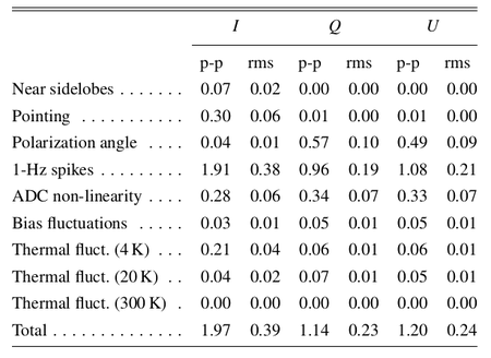
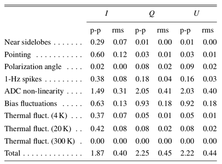
The impact of 1/ noise has been assessed using half-ring noise maps normalised to the white noise estimate at each pixel obtained from the white noise covariance matrix, so that a perfectly white noise map would be Gaussian and isotropic with unit variance. Deviations from unity trace the contribution of residual 1/f noise in the final maps, which ranges from 0.06% at 70 GHz to 2% at 30 GHz. Pixel uncertainties due to other systematic effects have been calculated on simulated maps degraded at Nside = 128 at 30 and 44 GHz and Nside = 256 at 70 GHz in order to approximate the optical beam size. This downgrading has been applied in all cases a systematic effect has been evaluated at map level.
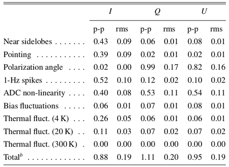
In Table 2 we list the r.m.s. and the difference between the 99% and the 1% quantities in the pixel value distributions. For simplicity we refer to this difference as peak-to-peak (p-p) difference although it neglects outliers but effectively approximates the peak-to-peak variation of the effect on the map.
Table 2. Summary of systematic effects uncertainties on maps in μKCMB.
|
|
|
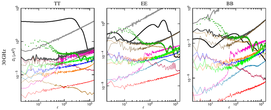
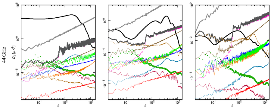
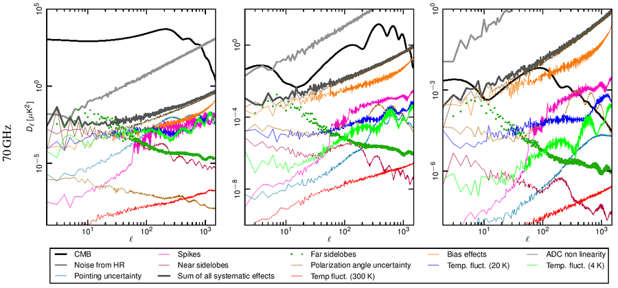
Angular power spectra have been obtained from full resolution (Nside = 1024) systematic effect maps at each frequency using HEALPix Anafast [4]. In Fig. 1 we show how the power spectrum of the various effects compared with the Planck best-fit spectra and with the noise level coming from the half-ring difference maps.
Our assessment shows that the global impact of systematic effects uncertainties in the LFI do not limit either temperature or E-mode spectra measurements.
Figure 1. Angular power spectra of the various systematic effects compared to the Planck beam-filtered temperature and polarization spectra. The dark-gray thick curve represents the total contribution. The dark-green dotted curve represent the contribution from far sidelobes that has been removed from the data and, therefore not considered in the total. The CMB TT and EE curves correspond to the Planck best-fit power spectra. The theoretical $B$-mode CMB spectrum assumes a tensor-to-scalar ratio r = 0.1, a tensor spectral index nT=0 and has not been beam-filtered. Rows: 30, 44 and 70 GHz spectra. Columns: temperature, E-mode and B-mode spectra. .
Detailed description of the various effects[edit]
A detailed description of the impact of the various effects is being prepared for the submission of a dedicated paper to A&A and will also appear on this supplement. We expect it to be available by the end of February.
References[edit]
- ↑ 1.01.11.2 Planck 2013 results. III. Low Frequency Instrument systematic uncertainties, Planck Collaboration, 2014, A&A, 571, A3.
- ↑ 2.02.12.2 Planck 2015 results. III. LFI systematics, Planck Collaboration, 2016, A&A, 594, A3.
- ↑ 3.003.013.023.033.043.053.063.073.083.093.103.11 Planck 2015 results. II. LFI processing, Planck Collaboration, 2016, A&A, 594, A2.
- ↑ HEALPix: A Framework for High-Resolution Discretization and Fast Analysis of Data Distributed on the Sphere, K. M. Górski, E. Hivon, A. J. Banday, B. D. Wandelt, F. K. Hansen, M. Reinecke, M. Bartelmann, ApJ, 622, 759-771, (2005).
(Planck) Low Frequency Instrument
Cosmic Microwave background
(Hierarchical Equal Area isoLatitude Pixelation of a sphere, <ref name="Template:Gorski2005">HEALPix: A Framework for High-Resolution Discretization and Fast Analysis of Data Distributed on the Sphere, K. M. Górski, E. Hivon, A. J. Banday, B. D. Wandelt, F. K. Hansen, M. Reinecke, M. Bartelmann, ApJ, 622, 759-771, (2005).
