2015 Sky temperature and polarization maps
Contents
- 1 General description
- 2 Production process
- 3 Types of maps
- 3.1 Full mission, full channel maps (6 HFI, 7 LFI)
- 3.2 Full mission light maps, full channel maps (6 HFI, 7 LFI)
- 3.3 Nominal mission, full channel maps (6 HFI)
- 3.4 Single survey, full channel maps (30 HFI, 35 LFI)
- 3.5 Year maps, full channel maps (12 HFI, 16 LFI)
- 3.6 Half-mission maps, full channel maps (12 HFI, 12 LFI)
- 3.7 Full mission, single detector maps (18 HFI, 22 LFI)
- 3.8 Full mission, detector set or detector pairs maps (8 HFI, 8 LFI)
- 3.9 Half-ring maps (64 HFI, 62 LFI)
- 3.10 The Zodiacal light correction maps
- 3.11 Caveats and known issues
- 4 Inputs
- 5 Related products
- 6 File names
- 7 FITS file structure
- 8 Polarization convention used in the Planck project
- 9 References
General description[edit]
Sky maps give the best estimate of the intensity and polarization (Stokes Q and U components), if available, of the signal from the sky after removal, as far as possible, of known systematic effects (mostly instrumental, but including also the solar and earth-motion dipole, Galactic strylight and the Zodiacal light). Sky maps are provided for the full Planck mission using all valid detectors in each frequency channel, and also for various subsets by splitting the mission in various time ranges or in subsets of the detectors in a given channel. These products are useful for the study of source variability, but they are especially interesting for characterisation purposes (see also the data validation section). The details of the start and end of the time ranges are given in the table below.
To help in further processing, there are also masks of the Galactic Plane and of point sources, each provided for several different depths.
All sky maps are in Healpix format, with Nside of 1024 (LFI 30, 44 and 70) and 2048 (LFI 70 and HFI), in Galactic coordinates, and Nested ordering.
- WARNING
- the Healpix convention for polarization is NOT the same as the IAU convention - see Section 8 in this page.
The signal is given in units of Kcmb for 30-353 GHz, and of MJy/sr (for a constant energy distribution ) for 545 and 857 GHz. For each frequency channel, the intensity and polarization maps are packaged into a BINTABLE extension of a FITS file together with a hit-count map (or hit map, for short, giving the number of observation samples that are cumulated in a pixel, all detectors combined) and with the variance and covariance maps. Additional information is given in the FITS file header. The structure of the FITS file is given in the FITS file structure section below.
- R2.00
- this first release (Jan 2015) contains polarisation data for the 353 GHz channel only.
- R2.01
- this second release (May 2015) adds polarisation data to the 100-217 GHz channels.
- R2.02
- a full re-release to correct the Healpix bad pixel value in the maps which was altered during the preparation of the maps and not reset to the correct value (the valid pixels are unchanged). It also fixes some FITS keywords, and includes a full re-release of the Zodi correction maps, with the 100-217 GHz one now including the polarisation correction)
| Range | ODs | HFI rings | pointing-IDs | Comment |
|---|---|---|---|---|
| nominal mission | 91 - 563 | 240 - 14723 | 00004200 - 03180200 | |
| full mission | 91 - 974 | 240 - 27005 | 00004200 - 05322620 | for HFI |
| full mission | 91 - 1543 | n/a | 00004200 - 06511160 | for LFI |
| Survey 1 | 91 - 270 | 240 - 5720 | 00004200 - 01059820 | |
| Survey 2 | 270 - 456 | 5721 - 11194 | 01059830 - 02114520 | |
| Survey 3 | 456 - 636 | 11195 - 16691 | 02114530 - 03193660 | |
| Survey 4 | 636 - 807 | 16692 - 21720 | 03193670 - 04243900 | |
| Survey 5 | 807 - 974 | 21721 - 27005 | 05267180 - 05322590 | end of mission for HFI |
| Survey 5 | 807 - 993 | n/a | 05267180 - 06344800 | end of survey for LFI |
| Survey 6 | 993 - 1177 | n/a | 06344810 - 06398120 | LFI only |
| Survey 7 | 1177 - 1358 | n/a | 06398130 - 06456410 | LFI only |
| Survey 8 | 1358 - 1543 | n/a | 06456420 - 06511160 | LFI only |
| Survey 9 | 1543 - 1604 | n/a | 06511170 - 06533320 | LFI only Not in this delivery |
| HFI mission-half-1 | 91 - 531 | 240 - 13471 | 00004200 - 03155580 | |
| HFI mission-half-2 | 531 - 974 | 13472 - 27005 | 03155590 - 05322590 | |
| LFI Year 1 | 91 - 456 | n/a | 00004200 - 02114520 | |
| LFI Year 2 | 456 - 807 | n/a | 02114530 - 04243900 | |
| LFI Year 3 | 807 - 1177 | n/a | 05267180 - 06398120 | |
| LFI Year 4 | 1177 - 1543 | n/a | 06398130 - 06511160 |
Production process[edit]
Sky maps are produced by combining appropriately the data of all working detectors in a frequency channel over some period of the mission. They give the best estimate of the signal from the sky (unpolarised) after removal, as far as possible, of known systematic effects and of the dipole signals induced by the motion of the solar system in the CMB and of the Planck satellite in the solar system. In particular, they include the Zodiacal light emission (Zodi for short) and also the scattering from the far-side lobes of the beams (FSL). More on this below.
HFI processing[edit]
The mapmaking and calibration process is described in detail in the Map-making section and in the Planck-2015-A08[1] paper, where detailed references are found. In brief it consists of:
- binning the TOI data onto rings
- Healpix rings (HPRs) are used here, each ring containing the combined data of one pointing period.
- flux calibration
- at 100-353 GHz, the flux calibration factors are determined by correlating the signal with the orbital dipole, which is determined very accurately from the Planck satellite orbital parameters provided by Flight Dynamics. This provides a single gain factor per bolometer. At 545 and 857 GHz the gain is determined from the observation of Uranus and Neptune (but not Jupiter which is too bright) and comparison to recent models made explicitly for this mission. A single gain is applied to all rings at these frequencies.
- destriping
- in order to remove low-frequency noise, an offset per ring is determined by minimizing the differences between HPRs at their crossings, and removed.
- Zodiacal light correction
- a Zodiacal light model is used to build HPRs of the the Zodi emission, which is subtracted from the calibrated HPRs.
- projection onto the map
- the offset-corrected, flux-calibrated, and Zodi-cleaned HPRs are projected onto Healpix maps, with the data of each bolometer weighted by a factor of 1/NET of that bolometer.
These steps are followed by some post-processing which is designed to prepare the maps for the component separation work. This post processing consists of:
- Dust bandpass leakage correction
- the Q and U maps are corrected for the intensity-to-polarisation leakage caused by the foregrounds having a non-CMB spectrum, and as a consequence of the non-identical bandpasses on the different detectors (bandpass mismatch, or BPM). This correction is determined using the ground method as described in Section 7.3 of Planck-2015-A08[1]. These correction maps can be found in the Planck Legacy Archive as HFI_CorrMap_???-dustleak-ground_2048_R2.0?_{coverage}.fits. The correction is applied by subtracting the correction map from the corresponding input map. This correction is not applied to the nominal mission maps, as indicated below, in order to maintain compatibility with the PR1 products. We stress that the correction applies only to the Q and U maps contained in the files; the temperature maps are not affected, and thus all temperature-only maps (like the 545 and 857 GHz channel maps and the single SWB maps) are not affected.
- Far Side Lobe calibration correction
- the 100-217 maps are multiplied by factors of 1.00087, 1.00046, and 1.00043, respectively, to compensate for the non-removal of the far-side lobes, and similarly the corresponding covariance maps have also been corrected by multiplication by the square of the factor.
- Fill missing pixels
- missing pixels are filled in with a value that is the mean of valid pixels within a given radius. A radius of 1 deg is used for the full channel maps, and 1.5 deg is used for the detset maps. This step is not applied to the single survey maps since they have large swaths of the sky that are not covered.
- Map zero-level
- for the 100 to 857 GHz maps, the zero levels are set to their optimal levels for Galactic and CIB studies. A procedure for adjusting them to astrophysical values is given in the HFI Mapmaking and Calibration paper Planck-2015-A08[1].
These maps provide the main mission products. Together with signal maps, hit count, variance, and variance maps are also produced. The hit maps give the (integer) number of valid TOI-level samples that contribute to the signal of each pixel. All valid samples are counted in the same way, i.e., there is no weighting factor applied. The variance maps project the white noise estimate, provided by the NETs, in the sky domain.
Note that the nominal mission maps have not had the post-processing applied, which makes them more easily comparable to the PR1 products.
LFI processing[edit]
LFI maps were constructed with the Madam map-making code, version 3.7.4. The code is based on generalized destriping technique, where the correlated noise component is modeled as a sequence of constant offset, called baselines. A noise filter was used to constrain the baseline solution allowing the use of 0.25 s and 1 second baselines for the 30 and 44, 70 GHz respectively.
Radiometers were combined according to the horn-uniform weighting scheme to minimize systematics. The used weights are listed in Map-making. The flagged samples were excluded from the analysis by setting their weights to = 0. The galaxy region was masked out in the destriping phase, to reduce error arising from strong signal gradients. The polarization component was included in the analysis...
- Dipole and Far Side Lobe correction
- input timelines are cleaned by 4pi convolved dipole and Galactic Straylight obtained as convolution of the 4pi in band far sidelobes and Galactic Simulation as explained in Section 7.4 of Planck-2015-A03[2].
Beam effects on the LFI maps are described in Section 7.1 of Planck-2015-A03[2]. Scaling of the maps due to beam effects is taken into account in the LFI's beam functions (as provided in the RIMO, give reference) which should be used for analysis of diffuse components. To compute the flux densities of compact sources, correction must be made for beam effects (see Table 8 of Planck-2015-A03[2])."
- Bandpass leakage correction
- as opposed to the HFI, the LFI high resolution maps have not been corrected for bandpass leakage. Only low resolution (nside 256) maps are provided with the bandpass correction. The correction maps (LFI_CorrMap_0??-BPassCorr_*.fits) can be found in the Planck Legacy Archive. Further details about the procedure used to generate the bandpass correction maps can be found in Section 11 of Planck-2015-A02[2].
- Map zero-level
- for the 30, 44 and 70 GHz, maps are corrected for zero level monopole by applying an offset correction, see LFI Calibration paper Planck-2015-A06[3]. Note that the offset applied is indicated in the header as a comment keyword.
A detailed description of the map-making procedure is given in Planck-2013-II[4], Planck-2015-A03[2], Planck-2015-A07[5] and in section Map-making.
Types of maps[edit]
Full mission, full channel maps (6 HFI, 7 LFI)[edit]
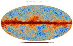
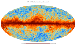
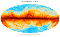
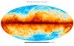
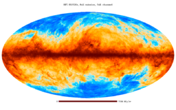
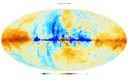
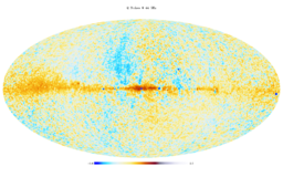
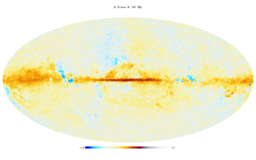
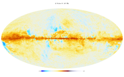
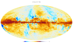
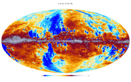
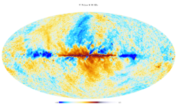
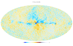
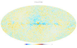
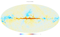
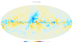
Full channel maps are built using all the valid detectors of a frequency channel and cover the either the full or the nominal mission. For HFI, the 143-8 and 545-3 bolometers are rejected entirely as they are seriously affected by RTS noise. HFI provides the Q and U components for the 100, 143, 217 and 353 GHz channels only. LFI provides the I, Q and U maps for all the channels. Reminder: HFI Q and U maps are corrected for bandpass leakage. LFI Q and U maps at Nside 1024 and 2048 are not corrected for bandpass leakage (shown as BPL uncorr in the PLA archive), but LFI nside 256 have been corrected for bandpass leakage.
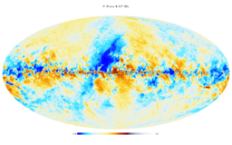
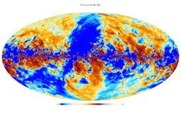
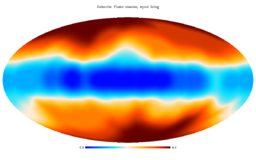
The I, Q and U maps are displayed in the figures below. The color range is set using a histogram equalisation scheme (from HEALPIX) that is useful for these non-Gaussian data fields. For visualization purposes, the Q and U maps shown here have been smoothed with a 1 degree Gaussian kernel, otherwise they look like noise to the naked eye. The 70 GHz full map is available also at 2048.
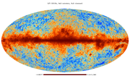
Full mission I, 30 GHz
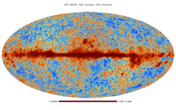
Full mission I, 44 GHz
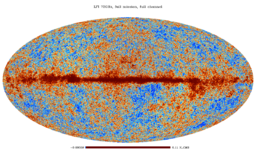
Full mission I, 70 GHz
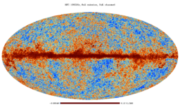
Full mission I, 100 GHz
Full mission I, 143 GHz
Full mission I, 217 GHz
Full mission I, 353 GHz
Full mission I, 545 GHz
Full mission I, 857 GHz


Full mission Q, 30 GHz
Full mission Q, 44 GHz

Full mission Q, 70 GHz
Full mission Q, 100 GHz
Full mission Q, 143 GHz
Full mission Q, 217 GHz
Full mission Q, 353 GHz


Full mission U, 30 GHz
Full mission U, 44 GHz
Full mission U, 70 GHz
Full mission U, 100 GHz
Full mission U, 143 GHz
Full mission U, 217 GHz
Full mission U, 353 GHz


Full mission light maps, full channel maps (6 HFI, 7 LFI)[edit]
These maps are based on the Full mission maps but contain fewer columns, IQU from 30 to 353 GHz, and I only at 545 and 857 GHz. These maps have been produced to reduce the transfer time of the most downloaded frequency full mission maps.
Nominal mission, full channel maps (6 HFI)[edit]
These maps are similar to the ones above, but cover the nominal mission only. They are meant primarily to be compared to the PR1 products in order to see the level of improvements in the processing. Because of this, they are produced in Temperature only, and have not had the post-processing applied.
Single survey, full channel maps (30 HFI, 35 LFI)[edit]
Single survey maps are built using all valid detectors of a frequency channel; they cover separately the different sky surveys. The surveys are defined as the times over which the satellite spin axis rotates but 180 degrees, which, due to the position of the detectors in the focal plane does not cover the full sky, but a fraction between ~80 and 90% depending on detector position. During adjacent surveys the sky is scanned in opposite directions. More precisely it is the ecliptic equator that is scanned in opposite directions. While these are useful to investigate variable sources, they are also used to study the systematics of the time-response of the detectors as they scan bright sources, like the Galactic Plane, in different directions during different survey. Note that the HFI and LFI missions cover 5 and 8 surveys, respectively, and in case of HFI the last survey in incomplete. The 70 GHz surveys maps are available also at 2048. Note LFI provide a special surveys maps combination used in the low l analysis. This maps, available at the three LFI frequency 30, 44 and 70 GHz, was built using the combination of survey 1, 3, 5, 6, 7 and 8.
Year maps, full channel maps (12 HFI, 16 LFI)[edit]
These maps are built using the data of surveys 1+2, surveys 3+4, and so forth. They are used to study long-term systematic effects. The 70 GHz years maps are available also at 2048.
Half-mission maps, full channel maps (12 HFI, 12 LFI)[edit]
For HFI, the half mission is defined after eliminating those rings discarded for all bolometers. There are 347 such rings, may of which are during the 5th survey when the End-of-Life tests were performed. The remaining 26419 rings are divided in half (up to the odd ring) to define the two halves of the mission. This exercise is done for the full mission only.
For LFI instead of the half-mission the following year combination has been created: Year 1+2, Year 1+3, Year 2+4, Year 3+4,
Full mission, single detector maps (18 HFI, 22 LFI)[edit]
IN case of HFI these maps are built only for the SWBs (non polarized) and contain only temperature data, of course. They are not built for the polarisation sensitive detectors because they are not fixed on the sky as the polarisation component depends on the position angle at the time of observation. Instead, we provide maps built by quads of polarisation-sensitive detectors (see next section), which have different polarisation angles and that can be used to built I, Q, and U maps
| Frequency | Detector names |
|---|---|
| 143 GHz | 143-5, 6, 7 |
| 217 GHz | 217-1, 2, 3, 4 |
| 353 GHz | 353-1, 2, 7, 8 |
| 545 GHz | 545-1, 2, 4 |
| 857 GHz | 857-1, 2 , 3, 4 |
The 143-8 and 353-3 bolometer data are affected by strong RTS (random telegraphic signal) noise. They have not been used in the data processing, and are not delivered. For a figure showing the focal plane layout, see this Introduction of the Detector Pointing chapter.
In case of LFI, all the 22 Radiometers maps are available, those, obviously, are only in temperature.
Full mission, detector set or detector pairs maps (8 HFI, 8 LFI)[edit]
The objective here is to build independent temperature (I) and polarisation (Q and U) maps with the two pairs of polarisation sensitive detectors of each channel where they are available, i.e. in the 44-353 GHz channels. The table below indicates which detectors were used to built each detector set (detset).
| Frequency | DetSet1 | DetSet2 |
|---|---|---|
| 100 GHz | 100-1a/b & 100-4a/b | 100-2a/b & 100-3a/b |
| 143 GHz | 143-1a/b 1 & 43-3a/b | 143-2a/b & 143-4a/b |
| 217 GHz | 217-5a/b & 217-7a/b | 217-6a/b & 217-8a/b |
| 353 GHz | 353-3a/b & 353-5a/b | 353-4a/b & 353-6a/b |
| Frequency | Horn Pair | Comment |
|---|---|---|
| 44 GHz | 24 | This maps is only in temperature |
| 44 GHz | 25 & 26 | |
| 70 GHz | 18 & 23 | Available also at = 2048 |
| 70 GHz | 19 & 22 | Available also at = 2048 |
| 70 GHz | 20 & 21 | Available also at = 2048 |
Half-ring maps (64 HFI, 62 LFI)[edit]
These maps are similar to the ones above, but are built using only the first or the second half of each ring (or pointing period). The HFI provides half-ring maps for the full mission only, and for the full channel, the detsets, and the single bolometers. The LFI provides half-rings maps for the channel full mission (70 GHz also at 2048), for the radiometer full mission and the horn pairs full mission.
The Zodiacal light correction maps[edit]
The Zodiacal light signal depends on the location of the observer relative to the Zodiacal light bands, and thus it is not a fixed pattern on the sky but depends on the period of observation. The maps presented here are the difference between the uncorrected (and not delivered) and the corrected maps.
Note that while the Zodiacal light model that is subtracted at ring level (see here) is not polarised, the corrections are not null and Q and U. This is suspected to come from some combination of leakage due to bandpass differences and beam mismatch, and maybe other effects. These leakages are typically of order a few %, at max, of the maximum zodi intensity at I for each channel. They range from ~150 nK at 100 GHz to ~5 uK at 353 GHz.
Caveats and known issues[edit]
- HFI polarization 100-217 GHz
- at low multipoles, despite the progress that has been made to control the systematic effects present in the maps, polarization data between 100-217 GHz are still contaminated by systematic residuals. Figure 10 of Planck-2015-A08[1] shows the EE power spectra from the half-difference maps at 100, 143, and 217 GHz and compared to the noise power spectrum from FFP8 simulations. he half-ring differences are compatible with noise while, at multipoles typically lower than 50, detector-set and half-mission differences are dominated by excess power which is larger than the EE CMB signal. The Planck Collaboration has used the range ell>30 to carry out component separation (Planck-2015-A09[6]), as data at ell<30 is not considered usable for cosmological analyses. The origin of the excess power will be explored in a forthcoming publication.
Inputs[edit]
HFI inputs[edit]
The HFI mapmaking takes as input:
- the cleaned TOIs of signal of each detector, together with their flags, produced by the TOI processing pipeline;
- the TOIs of pointing (quaternions), described in Detector pointing;
- bolometer-level characterization data, from the DPC's internal IMO (not distributed);
- Planck orbit data, used to compute and remove the Earth's dipole;
- Planck solar dipole information, used to calibrate the CMB channels;
- Planet models used to calibrate the Galactic channels.
LFI inputs[edit]
The Madam mapmaker takes as input:
- the calibrated timelines (for details see TOI Processing);
- the detector pointings (for details see Detector pointing);
- the noise information in the form of 3-parameter (white noise level, σ, slope, and knee frequency, fknee) noise model (for details see RIMO)
Related products[edit]
Masks[edit]
This section presents the masks of the point sources and of the Galactic plane. These are general purpose masks. Other masks specific to certain products are packaged with the products.
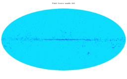
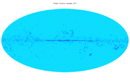
Point source masks[edit]
For HFI and LFI two sets of masks are provided:
- Intensity masks, which removes sources detected with SNR > 5.
- Polarisation masks, which remove sources which have polarisation detection significance of 99.97 % or greater at the position of a source detected in intensity. They were derived from the polarisation maps with dust ground bandpass mismatch leakage correction applied. The cut around each source has a radius of 3σ (width) of the beam ~ 1.27 FWHM (for LFI the cut around each source has a radius of 32 arcmin at 30GHz, 27 arcmin at 44 GHz and 13 arcmin at 70 GHz).
Both sets are found in the files HFI_Mask_PointSrc_2048_R2.00.fits and LFI_Mask_PointSrc_2048_R2.00.fits in which the first extension contains the Intensity masks, and the second contains the Polarisation masks.
Galactic plane masks[edit]
Eight masks are provided giving 20, 40, 60, 70, 80, 90, 97, and 99% sky coverage derived from the 353 GHz map, after CMB subtraction. They are independent of frequency channel. Three versions of these are given: not apodized, and apodized by 2 and 5 deg. The filenames are HFI_Mask_GalPlane-apoN_2048_R2.00.fits, where N = 0, 2, 5.
The masks are shows below. The 8 GalPlane masks are combined (added together) and shown in a single figure for each of the three apodization. While the result is quite clear for the case of no apodization, it is less so for the apodized case. The point source masks are shown separately for the Intensity case.
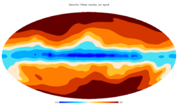
Galactic Plane masks, no apod
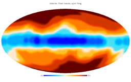
Galactic Plane masks, apod 2 deg
Galactic Plane masks, apod 5 deg
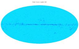
PointSource mask 100 GHz
PointSource mask 143 GHz
PointSource mask 217 GHz
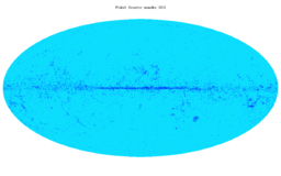
PointSource mask 343 GHz
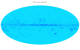
PointSource mask 545 GHz
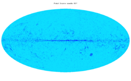
PointSource mask 857 GHz


File names[edit]
The FITS filenames are of the form {H|L}FI_SkyMap_fff{-tag}_Nside_R2.nn_{coverage}-{type}.fits, where fff are three digits to indicate the Planck frequency band, tag indicates the single detector or the detset, Nside is the Healpix Nside of the map, coverage indicates which part of the mission is covered (full, half mission, survey, year, ...) , and the optional type indicates the subset of input data used. The table below lists the products by type, with the appropriate unix wildcards that form the full filename.
| Coverage | filename | half-ring filename |
|---|---|---|
| Full chan, full mission | HFI_SkyMap_???_2048_R2.??_full.fits | HFI_SkyMap_???_2048_R2.??_full-ringhalf-?.fits |
| Full channel, nominal mission | HFI_SkyMap_???_2048_R2.??_nominal.fits | n/a |
| Full channel, single survey | HFI_SkyMap_???_2048_R2.??_survey-?.fits | n/a |
| Full channel, single year | HFI_SkyMap_???_2048_R2.??_year-?.fits | n/a |
| Full channel, half mission | HFI_SkyMap_???_2048_R2.??_halfmission*-?.fits | n/a |
| Det-set, full mission | HFI_SkyMap_???-ds?_2048_R2.??_full.fits | HFI_SkyMap_???-ds?_2048_R2.??_full-ringhalf-?.fits |
| Single SWB, full mission | HFI_SkyMap_???-?_2048_R2.??_full.fits | HFI_SkyMap_???-?_2048_R2.??_full-ringhalf-?.fits |
| Coverage | filename | half-ring filename | Comment |
|---|---|---|---|
| Full channel, full mission | LFI_SkyMap_???_1024_R2.??_full.fits | LFI_SkyMap_???_1024_R2.??_full-ringhalf-?.fits | Available also at Nside = 2048 |
| Full channel, single survey | LFI_SkyMap_???_1024_R2.??_survey-?.fits | n/a | Available also at Nside = 2048 |
| Full channel, survey combination | LFI_SkyMap_???_1024_R2.??_survey-1-3-5-6-7-8.fits | n/a | n/a |
| Full channel, single year | LFI_SkyMap_???_1024_R2.??_year-?.fits | n/a | Available also at Nside = 2048 |
| Full channel, year combination | LFI_SkyMap_???_1024_R2.??_year?-?.fits | n/a | n/a |
| Horn pair, full mission | LFI_SkyMap_???-??-??_1024_R2.??_full.fits | LFI_SkyMap_???_??-??_1024_R2.??_full-ringhalf-?.fits | Available also at Nside = 2048 |
| Single radiometer, full mission | LFI_SkyMap_???-???_1024_R2.??_full.fits | LFI_SkyMap_???-???_1024_R2.??_full-ringhalf-?.fits | n/a |
For the benefit of users who are only looking for the frequency maps with no additional information, we also provide a file combining the 9 frequency maps as separate columns in a single extension. The 9 columns in this file contain the intensity maps ONLY and no other information (hit maps and variance maps) is provided.
FITS file structure[edit]
The FITS files for the sky maps contain a minimal primary header with no data, and a BINTABLE extension (EXTENSION 1, EXTNAME = FREQ-MAP) containing the data. The structure is shows schematically in the figure below. The FREQ-MAP extension contains a 3- or a 10-column table that contain the signal, hit-count and variance maps, all in Healpix format. The 3-column case is for intensity only maps, the 10-column case is for polarisation. The number of rows is the number of map pixels, which is Npix = 12 2 for Healpix maps, where = 1024 or 2048 for most the maps presented in this chapter.

Note that file sizes are ~0.6 GB for I-only maps and ~1.9 GB for I,Q,U maps at 2048 and ~0.14 GB for I-only maps and ~0.45 GB for I,Q,U maps at 1024 .
Keywords indicate the coordinate system (GALACTIC), the Healpix ordering scheme (NESTED), the units (K_cmb or MJy/sr) of each column, and of course the frequency channel (FREQ). Where polarisation Q and U maps are provided, the COSMO polarisation convention (used in HEALPIX) is adopted, and it is specified in the POLCCONV keyword (see this section. The COMMENT fields give a one-line summary of the product, and some other information useful for traceability within the DPCs. The original filename is also given in the FILENAME keyword. The BAD_DATA keyword gives the value used by Healpix to indicate pixels for which no signal is present (these will also have a hit-count value of 0). The main parameters are summarised below:
| 1. EXTNAME = 'FREQ-MAP' : Data columns | |||
|---|---|---|---|
| Column Name | Data Type | Units | Description |
| I_STOKES | Real*4 | K_cmb or MJy/sr | The Stokes I map |
| Q_STOKES | Real*4 | K_cmb or MJy/sr | The Stokes Q map (optional) |
| U_STOKES | Real*4 | K_cmb or MJy/sr | The Stokes U map (optional) |
| HITS | Int*4 | none | The hit-count map |
| II_COV | Real*4 | K_cmb2 or (MJy/sr)2 | The II variance map |
| IQ_COV | Real*4 | K_cmb2 or (MJy/sr)2 | The IQ variance map (optional) |
| IU_COV | Real*4 | K_cmb2 or (MJy/sr)2 | The IQ variance map (optional) |
| QQ_COV | Real*4 | K_cmb2 or (MJy/sr)2 | The QQ variance map (optional) |
| QU_COV | Real*4 | K_cmb2 or (MJy/sr)2 | The QU variance map (optional) |
| UU_COV | Real*4 | K_cmb2 or (MJy/sr)2 | The UU variance map (optional) |
| Keyword | Data Type | Value | Description |
| PIXTYPE | string | HEALPIX | |
| COORDSYS | string | GALACTIC | Coordinate system |
| ORDERING | string | NESTED | Healpix ordering |
| POLCCONV | String | COSMO | Polarization convention |
| NSIDE | Int | 1024 or 2048 | Healpix |
| FIRSTPIX | Int*4 | 0 | First pixel number |
| LASTPIX | Int*4 | 12 2 – 1 | Last pixel number |
| FREQ | string | nnn | The frequency channel |
The same structure applies to all SkyMap products, independent of whether they are full channel, survey of half-ring. The distinction between the types of maps is present in the FITS filename (and in the traceability comment fields).
Polarization convention used in the Planck project[edit]
The Planck collaboration used the COSMO convention for the polarization angle (as usually used in space based CMB missions), whereas other astronomical fields usually use the IAU convention. In the following document we report the difference between these two conventions, and the consequence if it is NOT taken into account correctly in the analysis.

Changing the orientation convention is equivalent to a transformation of the polarization angle (Figure 1). The consequence of this transformation is the inversion of the Stokes parameter . The components of the polarization tensor in the helicity basis are:
where are the spin weighted spherical harmonic functions. The and modes can be defined as:
where the coefficients and are derived from linear combinations of the , defined implicitly in the first equation ().


The effect of the sign inversion of on the polarization spectra is a non trivial mixing of and modes.
An example of the typical error on and auto-spectra in case of a wrong choice of the polarization basis is shown in Figure 2.
BE CAREFUL about the polarization convention you are using. If the IAU convention is used in computing the power spectra, the sign of the component of the Planck maps must be inverted before computing and modes.
Note on the convention used by the Planck Catalogue of Compact Sources (PCCS)[edit]
For continuity with other compact sources catolgues, the Catalogue of Compact Sources provided by Planck follows the IAU convention, and the polarization angles are defined on an interval of [-90°,90°]. To switch to the COSMO convention, the polarization angles listed in the catalogue have to be shifted by 90° and multiplied by -1.
References[edit]
- ↑ 1.01.11.21.3 Planck 2015 results. VIII. High Frequency Instrument data processing: Calibration and maps, Planck Collaboration, 2016, A&A, 594, A8.
- ↑ 2.02.12.22.32.4 Planck 2015 results. II. LFI processing, Planck Collaboration, 2016, A&A, 594, A2.
- ↑ Planck 2015 results. V. LFI calibration, Planck Collaboration, 2016, A&A, 594, A5.
- ↑ Planck 2013 results. II. Low Frequency Instrument data processing, Planck Collaboration, 2014, A&A, 571, A2
- ↑ Planck 2015 results. VI. LFI mapmaking, Planck Collaboration, 2016, A&A, 594, A6.
- ↑ Planck 2015 results. XI. Diffuse component separation: CMB maps, Planck Collaboration, 2016, A&A, 594, A9.
(Planck) Low Frequency Instrument
(Planck) High Frequency Instrument
Flexible Image Transfer Specification
Cosmic Microwave background
[LFI meaning]: absolute calibration refers to the 0th order calibration for each channel, 1 single number, while the relative calibration refers to the component of the calibration that varies pointing period by pointing period.
Noise Equivalent Temperature
reduced IMO
random telegraphic signal
Planck Legacy Archive
Data Processing Center
Full-Width-at-Half-Maximum