LFI design, qualification, and performance
Contents
Overview[edit]
The first :
- uno
- due
- tre
- quattro
Only a.
Each LFI radiometer g , signals at the frequency of the phase switch. By changing the phase switches configuration, the output can be a sequence of either or signals.
The Planck-LFI instrument is an array of 11 radiometric receivers in the Ka, Q and V bands, with centre frequencies close to 30, 44 and 70 GHz. The exact centre frequencies for each receiver are reported in [A. Mennella, M. Bersanelli, R. C. Butler et al. Planck early results. III. First assessment of the Low Frequency Instrument in-flight performance. A&A, 536:A3, 2011]; for simplicity, here we will refer to the three channels using their nominal centre frequency. A detailed description of the LFI instrument is given in [M. Bersanelli, N. Mandolesi, R. C. Butler et al. Planck pre-launch status: Design and description of the Low Frequency Instrument. A&A, 520:A4, 2010], and references therein.
The LFI description[edit]
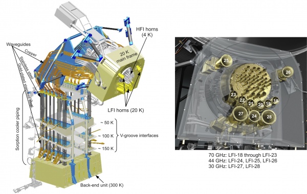
The LFI instrument (see figure below) consists of a 20 K focal plane unit hosting the corrugated feed horns, the orthomode transducers (OMTs) and the receiver front-end modules (FEMs). Fourty four composite waveguides [O. D’Arcangelo, L. Figini, A. Simonetto et al. The Planck-LFI flight model composite waveguides. Journal of Instrumentation, 4:2007, 2009] are interfaced with three conical thermal shields and connect the front-end modules to the warm (~300 K) back-end unit (BEU) containing a further radio frequency amplification stage, detector diodes and all the electronics for data acquisition and bias supply.
Best LFI noise performance is obtained with receivers based on InP High Electron Mobility Transistor (HEMT) low noise amplifiers (LNAs) for minimal power dissipation and best performance. To further minimise power consumption in the focal plane, the radiometers are split into two sub-assemblies connected by waveguides, one located at the telescope focal area, the other on the 300 K portion of the Planck satellite. These design features allow the entire front-end LNAs dissipation to be <0.55 W, which enables the active cooling of the focal assembly. This is achieved with a vibration-less hydrogen sorption cooler, which also provides 18 K pre-cooling to the HFI helium J-T cooler. Because the sorption cooler is necessary to both LFI and HFI, a redundant cooler is included in the flight hardware.
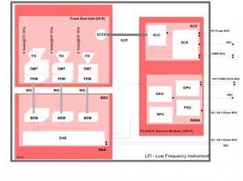
As shown schematically in figure below, the LFI consists of the following subsystems:
- Radiometer Array Assembly (RAA)
- Sorption Cooler Subsystem (SCS)
- Radiometer Electronics Box Assembly (REBA)
The RAA includes the Front End Unit (FEU) and the Back End Unit (BEU), connected via waveguides. The FEU is located at the focus of the telescope, as one component of the joint LFI/HFI focal assembly (see Section 3.4). The BEU is mounted on the top of the Planck SVM. The Radiometer Electronics Box Assembly (REBA) and the warm parts of the Sorption Cooler System (SCS) is located on one of the lateral panels of the service module (SVM). The FEU and the Sorption Cooler Compressor (SCC) are connected by concentric stainless steel tubes. The smaller tube carries hydrogen at ∼60 atmospheres from the cooler compressors to the FEU, while the larger tube returns the hydrogen at ∼0.3 atmospheres. These units are described in detail in following sections. All LFI units are linked together by the LFI harness, which also connects to the spacecraft interface.
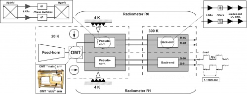
Every radiometer chain assembly (RCA) consists of two radiometers, each feeding two diode detectors (see figure below), for a total of 44 detectors. The 11 RCAs are labelled by a numbers from 18 to 28 as outlined in Figure 1, right panel.
Figure 3 provides a more detailed description of each radiometric receiver. In each RCA, the two perpendicular linear polarisation components split by the OMT propagate through two independent pseudo-correlation differential radiometers, labelled as M or S depending on the arm of the OMT they are connected to (Main or Side, see lower-left inset of Figure 3).
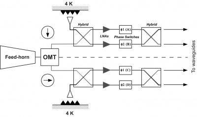
In each radiometer the sky signal coming from the OMT output is continuously compared with a stable 4 K blackbody reference load mounted on the external shield of the HFI 4 K box [L. Valenziano, F. Cuttaia, A. De Rosa et al. Planck-LFI: design and performance of the 4 Kelvin Reference Load Unit. Journal of Instrumentation, 4:2006, 2009.]. After being summed by a first hybrid coupler, the two signals are amplified by ~30 dB, see upper-left inset of Figure 3. The amplifiers were selected for best operation at low drain voltages and for gain and phase match between paired radiometer legs, which is crucial for good balance. Each amplifier is labelled with codes 1, 2 so that the four outputs of the LNAs can be named with the sequence: M1, M2 (radiometer M) and S1, S2 (radiometer S). Tight mass and power constraints called for a simple design of the Data Acquisition Electronics (DAE) box so that power bias lines were divided into five common-grounded power groups with no bias voltage readouts; only the total drain current flowing through the front-end amplifiers is measured and is available to the house-keeping telemetry (this design has important implications for front-end bias tuning, which depends critically on the satellite electrical and thermal configuration and was repeated at all integration stages, during on-ground and in-flight satellite tests). A phase shift alternating between and at the frequency of 4096 Hz is applied in one of the two amplification chains and then a second hybrid coupler separates back the sky and reference load components that are further amplified and detected in the warm BEU, with a voltage output ranging from -2.5 V to +2.5 V.
Each radiometer has two output diodes which are labelled with binary codes 00, 01 (radiometer M) and 10, 11 (radiometer S), so that the four outputs of each radiometric chain can be named with the sequence: M-00, M-01, S-10, S-11.
After detection, an analog circuit in the DAE box removes a programmable offset in order to obtain a nearly null DC output voltage and a programmable gain is applied to increase the signal dynamics and optimally exploit the ADC input range. After the ADC, data are digitally downsampled, requantised and compressed in the radiometer electronics box assembly (REBA) according to a scheme described in [J. M. Herreros, M. F. Gómez, R. Rebolo et al. The Planck-LFI Radiometer Electronics Box Assembly. Journal of Instrumentation, 4:2008, 2009; M. Maris, M. Tomasi, S. Galeotta et al. Optimization of Planck-LFI on-board data handling. Journal of Instrumentation, 4:2018, 2009.] before preparing telemetry packets. On ground, telemetry packets are converted to sky and reference load time ordered data after calibrating the ADU samples into volt considering the applied offset and gain factors.
To first order, the mean differential power output for each of the four receiver diodes can be written as follows [M. Seiffert, A. Mennella, C. Burigana et al. 1/f noise and other systematic effects in the Planck-LFI radiometers. A&A, 391:1185–1197, 2002; A. Mennella, M. Bersanelli, M. Seiffert et al. Offset balancing in pseudo-correlation radiometers for CMB measurements. A&A, 410:1089–1100, 2003; M. Bersanelli, N. Mandolesi, R. C. Butler et al. Planck pre-launch status: Design and description of the Low Frequency Instrument. A&A, 520:A4, 2010]:
where is the total gain, is the Boltzmann constant, the receiver bandwidth and is the diode constant. and are the average sky and reference load antenna temperatures at the inputs of the first hybrid and is the receiver noise temperature.
The gain modulation factor [A. Mennella, M. Bersanelli, M. Seiffert et al. Offset balancing in pseudo-correlation radiometers for CMB measurements. A&A, 410:1089–1100, 2003; A. Zacchei, D. Maino, C. Baccigalupi et al. Planck early results. V. The Low Frequency Instrument data processing. A&A, 536:A5, 2011], , is defined by:
and is used to balance (in software) the temperature offset between the sky and reference load signals and minimise the residual 1/ noise in the differential datastream. This parameter is calculated from the average uncalibrated total power data using the relationship:
where and are the average sky and reference voltages calculated in a defined time range. The white noise spectral density at the output of each diode is essentially independent from the reference-load absolute temperature and is given by:
- Radiometer Chain Overall Design
- Radiometer Array Assembly
- REBA
- Radiometer Chain Overall Design
- Instrument On-board Software
- Instrument Operations
- Instrument Budgets
LFI Ground Tests[edit]
LFI In-flight Calibration[edit]
LFI Performance[edit]
- Instrument Scientific Performance
- Instrument Technical Performance
(Planck) Low Frequency Instrument
LFI warm electronics Back End Unit
High Electron Mobility Transistor
(Planck) High Frequency Instrument
LFI Radiometer Array Assembly
Sorption Cooler Subsystem (Planck)
LFI Radiometer Electronics Box Assembly
LFI cryogenic amplifying stage Front End Unit
Service Module
Sorption Cooler Compressor assembly
LFI Radiometer Chain Assembly
LFI Ortho Module Transducer
LFI Data Acquisition Electronics
analog to digital converter
Cosmic Microwave background


