Difference between revisions of "Survey scanning and performance"
(→Data gap recoveries) |
|||
| (115 intermediate revisions by 2 users not shown) | |||
| Line 1: | Line 1: | ||
| + | == The observation strategy == | ||
| − | + | The Planck ''observation strategy'', or ''scanning strategy'', makes use of the characteristics of the Planck spacecraft {{PlanckPapers|planck2011-1-1}} and orbit in order to achieve the survey goals in terms of sky coverage and scanning directions. | |
| − | The | ||
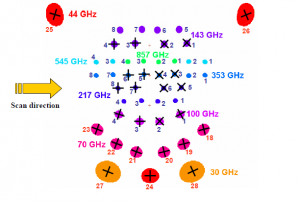
| − | + | The Planck focal plane scans the sky in the way explained in the figure below. | |
| − | The | ||
| − | |||
| − | + | [[file:FocalPlane.png|thumb|300px|The Planck focal plane with the direction of scanning. Polarization-sensitive detectors are drawn with crosses indicating the polarization direction.]] | |
| − | The | ||
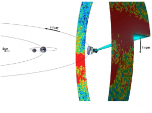
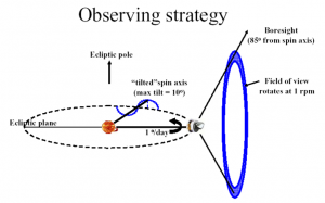
| − | + | The 353 GHz row scans the sky in small circles with a 85 deg. bore-sight angle from the spin axis. 545 GHz, 857 GHz, 143 GHz bolometers as well as LFI 25-26 radiometers have a slightly smaller bore-sight angle, while the other part of the Planck focal plane have larger ones (up to ~ 89 deg.). The Planck spacecraft spins at a rate of 1 rpm. | |
| − | |||
| − | + | Planck, being at L2, moves along the Ecliptic at ~ one degree per day, and needs to keep the Solar aspect angle below ~ 9 degrees at all times. In practice, during the surveys, the limit considered is 8 deg. Another celestial constraint is that the angle between the Planck spin axis and the anti-Earth direction cannot exceed 15 deg. (relaxed to 17 deg. from Survey 5 onward). These constraints have a very direct influence on the chosen scanning strategy. | |
| − | The reasons to decide to use such a precession of the spin axis are | + | [[File:ScannStrategy.png|thumb|300px|Simplified way to show the Planck scanning strategy, without additional motion of the spin axis]] |
| − | + | ||
| − | + | [[File:Observing_strat.png|thumb|300px|left|The Planck scanning strategy with the additional motion of the spin axis.]] | |
| + | |||
| + | The path followed by the Planck spin axis is defined with respect to the Ecliptic plane. It corresponds to a motion in longitude which maintains an anti-Sun pointing (about one degree per day), to which is added a cycloidal motion (precession) of the spin axis around the anti-Sun position (fiducial point). The cycloidal path is defined by the following functions: | ||
| + | |||
| + | $ λ = θ sin((-1)^n ω (t-t_0)+φ) $ (eq. 1) | ||
| + | |||
| + | $β = -θ cos((-1)^n ω(t-t_0) + φ) $ (eq. 2) | ||
| + | |||
| + | where λ is the angular distance from the fiducial point in Ecliptic longitude, β the angular distance from the fiducial point in Ecliptic latitude, θ the spin axis precession amplitude, ω the pulsation of the precession, φ its phase, n the parameter which controls the motion direction of the precession, t is the time, and $t_0$ is the first time during the Planck survey at which the fiducial point crosses the 0 Ecliptic longitude line. | ||
| + | |||
| + | [[File:Cycloidal_scanning.JPG|thumb|300px|Spin axis path with a 7 degree amplitude cycloidal scanning, from {{BibCite|dupac2005}}]] | ||
| + | |||
| + | The reasons to decide to use such a precession of the spin axis are the following : | ||
| + | |||
| + | * An excursion of the spin axis from the anti-Sun direction is required to fully observe the whole sky (no excursion would leave a large area unobserved around the Ecliptic poles) | ||
| + | |||
| + | * The precession motion allows to keep the Sun aspect angle constant during the whole survey, therefore minimizing the thermal constraint variations on the spacecraft | ||
The following precession parameters have been chosen for the BSS: | The following precession parameters have been chosen for the BSS: | ||
| − | + | ||
| − | + | * amplitude $θ = 7.5^o$ (this value is the lowest possible which allows to cover the whole sky with all detectors) | |
| − | + | ||
| − | + | * n = 1 (anti-clockwise motion as seen from the Sun) | |
| − | + | ||
| − | + | * pulsation ω = 2π / (half a year). Faster precession was considered, and has interesting advantages, but is not possible given the constraints if one wants to keep a 7.5 deg. amplitude (which is necessary to cover the whole sky). | |
| − | + | ||
| − | + | * The phase of the precession was decided according to this set of criteria (in order of importance): | |
| − | + | ||
| − | + | a) respecting the operational constraints, | |
| + | |||
| + | b) allowing the largest possible angle between two scans on the Crab, | ||
| + | |||
| + | c) avoiding null dipole amplitude for the whole mission, | ||
| + | |||
| + | d) optimizing the position of the planets in the beginning of the survey and with respect to the feasibility of their recovery, | ||
| + | |||
| + | e) placing the two “deep fields” where Galactic foregrounds are minimum, | ||
| + | |||
| + | f) allowing a reasonable survey margin (i.e. the time allowed to recover lost pointings if a problem occurs) | ||
| + | |||
| + | The phase is 340 deg. for Surveys 1 to 4, and 250 deg. for Surveys 5 to 8. | ||
| + | |||
| + | The scanning strategy for the second year of Routine Operations (i.e. Surveys 3 and 4) is exactly the same as for the first year, except that all pointings are shifted by 1 arcmin along the cross-scanning direction, in order to provide finer sky sampling for the highest frequency detectors when combining two years of observations. | ||
| + | |||
| + | The change of phase between Survey 4 and Survey 5 occurred because it was found essential especially on the HFI side that scanning direction crossings are increased in the Planck survey. By choosing a phase 90 deg. away from the original one, one optimizes the scanning strategy in this respect. | ||
The details of the justifications for these parameters can be found in PL-WG9-TN-001. | The details of the justifications for these parameters can be found in PL-WG9-TN-001. | ||
| − | |||
| − | |||
| − | The motion of the spin axis is not continuous. Every change in the spin axis position | + | The scanning strategy parameters are input to the PSO Survey Planning and Performance Tool, which is the software which generates the series of pointing records to be sent out to MOC for implementation. |
| + | |||
| + | An approximate visualisation of the Planck scanning strategy can be found [http://www.youtube.com/watch?v=WwFXuZ0B3B8 here] and [http://www.youtube.com/watch?v=7Zu-aiEiDtY here]. | ||
| + | |||
| + | ===Spin axis manoeuvres and exact pointings=== | ||
| + | The motion of the spin axis is not continuous. Every change in the spin axis position is initiated by a manoeuvre which requires less than 5 minutes time to complete. | ||
| + | |||
| + | The duration between spin-axis manoeuvres is hereafter referred to as “dwelling times"; and the angular distance between manoeuvres along the spin axis path is hereafter referred to as “spacing”. | ||
| + | |||
| + | The dwelling times and spacings are defined as follows: | ||
| + | |||
| + | * The spacings are fixed to 2’ which roughly corresponds to Nyquist criterion for sampling the highest-frequency HFI detectors. | ||
| + | |||
| + | * The dwell times vary from 2360 s to 3904 s. | ||
| + | The exact series of coordinates and dwell times are set by equations 1 and 2 when one has fixed the spacings. | ||
| + | |||
| + | == Data gap recoveries == | ||
| + | |||
| + | Gaps in the data flow can occur because of various reasons: | ||
| + | |||
| + | * Anomalies may occur at spacecraft or instrument level, but also due to failures in the ground-to-spacecraft link or the ground segment itself. The adverse effects of such anomalies may be the loss of scientific data corresponding to one or several planned pointings, which have either not been acquired and/or stored in memory. | ||
| + | |||
| + | * Failure to acquire proper scientific data may occur to one or both instruments | ||
| + | |||
| + | In case a gap occurs, scientific criteria are applied to decide whether to recover the data through the Small-Gap Recovery procedure. | ||
| + | |||
| + | [[File:AHF_353_OD389.png|thumb|400px|The 353 GHz detectors {{PlanckPapers|lamarre2010}} integration time after 389 Operational Days (the unit is seconds per square degree, normalized to one detector). The first significant data gap and recovery are clearly visible.]] | ||
| + | |||
| + | The Small-Gap Recovery (SGR) procedure can be applied by MOC or PSO: | ||
| + | |||
| + | * '''MOC-triggered SGR''': Within its nominal scheduling procedure for an OD, the MOC searches the PPL for PREF corresponding to the OD being processed and any pointings which are subject of a Small Gap Recovery. As the PREF are sorted in chronological order according to their nominal start time, those corresponding to a small gap will naturally be the earliest. After checking attitude constraints, all observable pointings are listed and their dwell times reduced (initially) to the Minimum Dwell Time (MDT) as given in the PPL. | ||
| + | Having included all valid PREF the required slew times are calculated. With the required slew times and minimum dwell times for all pointings, the OD schedule may be under-populated; in this case the dwell times of all scheduled pointings will be increased equally to make use of all available time in the OD. If the resulting schedule is over-populated, even with MDT for all pointings, the recovery cannot be constrained to a single OD. The sequence of pointings for the ODs involved will be optimized in PREF scheduling and dwell times in order to effect the recovery and revert to the nominal timeline as quickly as possible. | ||
| + | |||
| + | * '''PSO-triggered SGR''': | ||
| + | PSO declares a small gap when pointings that have been executed result in data of insufficient quality or inadequate frequency coverage. This assessment is based on data quality and instrument health information provided by the DPCs. The algorithm that is used by the PSO to check the scientific validity of a pointing is implemented within the SPPT software tool. The SPPT ingests on a weekly basis a Weekly Health Report (WHR) for the HFI and LFI containing information on the current working status of each detector and their expected condition over the next four weeks. On a daily basis, a Daily Quality Report (DQR) provided by the DPCs for both instruments, includes a set of parameters that describe the quality of the detection achieved by each individual detector for every pointing executed. | ||
| + | |||
| + | The scheme for declaring a Small-Gap Recovery from PSO is the following: | ||
| + | |||
| + | - If a pointing fails to meet the chosen requirement, it becomes an SGR candidate | ||
| + | |||
| + | - If there are at least 12 consecutive pointings which are declared SGR candidates, and the problem has been identified and solved, then an SGR is triggered | ||
| + | Recoveries are only carried out if the recovery slewing out is guaranteed to be in OCM. MOC carries out this analysis and decides whether they perform the SGR accordingly. | ||
| + | |||
| + | - The start and end times of the gap and the list of the pointing numbers (or just the numbers of the first and last pointings to be recovered) are then sent to MOC by E-mail, with the notification to start a Small-Gap Recovery | ||
| + | |||
| + | - MOC implements the Small-Gap Recovery, provided the pointings can still be scheduled with respect to their latest start time, using the same scheme as described in the MOC-triggered SGR section | ||
| + | |||
| + | Throughout the Planck mission, data losses have been very rare. Small-Gap Recovery has been applied only a couple of times. | ||
| + | |||
| + | ==Special observations== | ||
| + | The special observations are: | ||
| + | |||
| + | * normal scanning on Solar System objects for calibration purposes | ||
| + | |||
| + | [[File:Crab_Nebula.jpg|thumb|200px|The Crab Nebula (Messier 1, NGC 1952, Taurus A), here seen by the Hubble Space Telescope]] | ||
| + | |||
| + | [[File:Mars.jpg|thumb|200px|Mars as seen by the Hubble Space Telescope in 1999]] | ||
| + | |||
| + | This concerns the following objects (planets): Mars, Jupiter, Saturn, Uranus and Neptune whose thermal emission in the far-infrared and their point-source-like quality make them essential calibrators for spider-web bolometers and radiometers. | ||
| + | |||
| + | Mars is a particularly interesting calibrator for Planck because of its proper motion. | ||
| + | However this proper motion makes it difficult to observe it many times during the mission. | ||
| + | |||
| + | Jupiter is the brightest source for (non-polarized) calibration. Saturn is also used a lot, and Uranus and Neptune are secondary calibrators. | ||
| + | |||
| + | * normal scanning on other (non-moving) sources for calibration purposes | ||
| + | |||
| + | This concerns mostly the Crab Nebula for polarizer calibration purposes. | ||
| + | This supernova remnant is highly polarized and as such represents the main polarization calibrator for Planck. | ||
| − | + | * special pointings during the calibration phase, not relative to celestial sources | |
| − | + | * "deep rings" : these special observations are performed on each passage of Jupiter and the Crab Nebula, from January 2012 onward. | |
| − | |||
| − | |||
| − | |||
| + | They consist of very deeply sampled observations (0.5') with the spin axis along the Ecliptic plane, during typically two to three weeks. | ||
| − | + | These observations benefit from special relaxing of the celestial constraints with Solar Aspect Angles < 9 deg. rather than < 8 deg. during cycloidal surveying. | |
| − | + | * "drift scans" : these special observations are performed on Mars, making use of its proper motion | |
| − | |||
| − | |||
| − | |||
| − | |||
| − | |||
| − | |||
| + | ==Start and end of surveys== | ||
| + | The completion of a given “survey” is declared when the logical AND of all frequency-coverage maps is greater than 95 %, OR the sky has been surveyed over a consecutive period of 7.5 months. Note that this definition is that of the Project Scientist and Planck Science Office. Data Processing Centres do not use the same concept of surveys to create "survey" maps. | ||
| − | + | In practice, since the gaps during the surveys have always been very small, it results in ~ six months per survey. | |
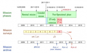
| + | [[File:PlanckMissionTimeline.JPG|thumb|300px|The Planck mission timeline with the distribution of the "sky surveys".]] | ||
| − | + | * '''Survey 1''': starts August 13, 2009, ends Feb. 13, 2010 | |
| − | + | * '''Survey 2''': starts Feb. 14, 2010, ends Aug. 13, 2010 | |
| − | Survey | + | * '''Survey 3''': starts Aug. 14, 2010, ends Feb. 13, 2011 |
| − | |||
| − | |||
| − | |||
| − | |||
| − | |||
| − | |||
| − | |||
| − | |||
| − | |||
| − | |||
| − | + | * '''Survey 4''': starts Feb. 14, 2011, ends July 29th, 2011 | |
| − | |||
| − | |||
| − | |||
| + | This survey was shortened in ordered to start earlier with the new scanning strategy (see above). | ||
| − | + | * '''Survey 5''': starts July 29th, 2011, ends January 30th, 2012 | |
| − | |||
| − | |||
| − | |||
| − | |||
| − | |||
| − | |||
| − | |||
| − | |||
| − | |||
| − | |||
| − | |||
| − | |||
| − | |||
| + | * '''Survey 6''' (LFI only): starts January 30th, 2012, ends July 31st, 2012 | ||
| − | + | * '''Survey 7''' (LFI only): starts July 31st, 2012, ends January 31st, 2013 | |
| − | |||
| − | |||
| − | LFI | ||
| − | |||
| − | |||
| − | |||
| − | |||
| − | |||
| + | * '''Survey 8''' (LFI only): starts February 1st, 2013, ends August 1st, 2013 | ||
| + | === Completion of full sky coverage during Surveys 1-2 === | ||
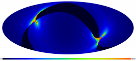
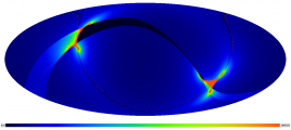
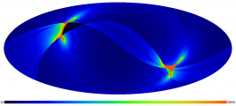
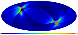
| − | + | The picture gallery below exhibits the progress of sky coverage during the first months of survey (black color = unobserved areas). | |
| − | |||
| − | |||
| − | |||
| − | |||
| − | |||
| − | 5. | + | <gallery widths=330 perrow=3 caption="The HFI 353 GHz integration time after N months of survey. Unit is seconds per square degree, normalized to one detector."> |
| + | File:353_1month.png|After 1 month | ||
| + | File:353_2month.png|After 2 months | ||
| + | File:353_3month.png|After 3 months | ||
| + | File:353_4month.png|After 4 months | ||
| + | File:353_5month.png|After 5 months | ||
| + | File:353_6month.png|After 6 months | ||
| + | File:353_7month.png|After 7 months | ||
| + | File:353_8month.png|After 8 months | ||
| + | File:353_9months.png|After 9 months | ||
| + | File:353_10months.png|After 10 months | ||
| + | File:353_11months.png|After 11 months | ||
| + | File:353_12months.png|After 12 months | ||
| + | </gallery> | ||
| − | + | == Main planet and Crab observations during Surveys 1-7 == | |
| − | |||
| − | |||
| − | |||
| + | Solar System objects and the Crab Nebula have been observed many times during the Planck surveys. Here is a complete list of these observations. Note that the ''deep rings'' and ''drift scans'' (Mars only) are in '''boldface'''. | ||
| + | * Crab: Sept. 16-22, 2009 | ||
| + | * Mars: Oct. 17-29, 2009 | ||
| − | + | * Jupiter: Oct. 25 – Nov. 1, 2009 | |
| − | |||
| − | |||
| − | |||
| − | |||
| − | |||
| − | |||
| − | |||
| − | |||
| − | |||
| − | |||
| − | |||
| − | |||
| − | |||
| + | * Neptune: Nov. 1-8, 2009 | ||
| − | + | * Uranus: Dec. 6-16, 2009 | |
| − | |||
| − | |||
| − | |||
| − | |||
| − | |||
| − | |||
| − | |||
| − | |||
| + | * Saturn: Jan. 2-8, 2010 | ||
| + | * Crab: March 6-12, 2010 | ||
| − | + | * Mars: April 9-18, 2010 | |
| − | + | * Neptune: May 15-23, 2010 | |
| + | * Saturn: June 13-22, 2010 | ||
| − | + | * Uranus: June 27 – July 5, 2010 | |
| − | |||
| − | + | * Jupiter: July 1-9, 2010 | |
| − | |||
| − | + | * Crab: Sept. 15-21, 2010 | |
| − | |||
| − | + | * Neptune: Nov. 3-11, 2010 | |
| − | |||
| − | + | * Jupiter: Dec. 9-18, 2010 | |
| − | + | * Uranus: Dec. 12-21, 2010 | |
| − | |||
| − | + | * Saturn: Jan. 15-22, 2011 | |
| − | |||
| − | + | * Crab: March 7-12, 2011 | |
| − | |||
| − | Neptune | + | * Neptune: May 18-26, 2011 |
| − | |||
| − | + | * Saturn: June 30 - July 9, 2011 | |
| − | |||
| − | + | * Uranus: July 3-11, 2011 | |
| − | |||
| − | + | * Jupiter: Aug. 9-15, 2011 | |
| − | |||
| − | + | * Crab: Sept. 10-18, 2011 | |
| − | |||
| − | + | This Crab scan was performed with the 250 deg. phase cycloidal strategy. | |
| − | |||
| − | + | * Crab: Sept. 20-23, 2011 | |
| − | |||
| − | + | This Crab scan was performed with the 340 deg. phase cycloidal strategy. | |
| − | |||
| − | + | * '''Mars''': Dec. 8-16, 2011 ("drift scan": Mars is let move through the Planck focal plane via its proper motion) | |
| − | |||
| − | + | * Mars: Dec. 17-26, 2011 (normal scanning) | |
| − | |||
| − | + | * '''Jupiter''': Jan. 8-30, 2012 (deep ring) | |
| − | |||
| − | + | * '''Crab''': Feb. 26 - March 16, 2012 (deep ring) | |
| − | |||
| − | + | * '''Jupiter''': Sept. 1-14, 2012 (deep ring) | |
| − | |||
| − | + | * '''Crab''': Sept. 14 - Oct. 1, 2012 (deep ring) | |
| − | |||
| − | + | * Neptune: Nov. 19-27, 2012 | |
| − | |||
| − | + | * Uranus: Dec. 24-30, 2012 | |
| − | |||
| − | Saturn | + | * Saturn: Jan. 30 - Feb. 5, 2013 |
| − | |||
| − | + | * '''Jupiter''': Feb. 2013 (deep ring) | |
| − | |||
| − | + | == Resulting integration time distribution == | |
| − | |||
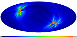
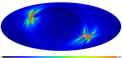
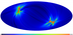
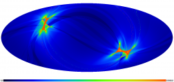
| + | The integration time after the end of HFI operations (January 2012) is shown in the following picture gallery. | ||
| + | Units are seconds per square degree, normalized to one detector, for all maps. The projection is full-sky Mollweide centered on the Galactic Centre. | ||
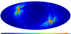
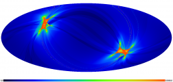
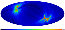
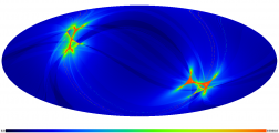
| + | <gallery widths=330px perrow=3 caption="Integration time after the end of HFI operations (January 2012). Units are seconds per square degree, normalized to one detector."> | ||
| + | File:HFI_fullmission_100GHz1-4.png|HFI 100 GHz 1,4 | ||
| + | File:HFI_fullmission_100GHz2-3.png|HFI 100 GHz 2,3 | ||
| + | File:HFI_fullmission_143GHz1-4.png|HFI 143 GHz 1-4 | ||
| + | File:HFI_fullmission_143GHz5-8.png|HFI 143 GHz 5-8 | ||
| + | File:HFI_fullmission_217GHz1-4.png|HFI 217 GHz 1-4 | ||
| + | File:HFI_fullmission_217GHz5-8.png|HFI 217 GHz 5-8 | ||
| + | File:HFI_fullmission_353GHz.png|HFI 353 GHz | ||
| + | File:HFI_fullmission_545-857GHz.png|HFI 545 GHz / 857 GHz | ||
| + | File:LFI25_coldmission.png|LFI-25 (44 GHz) | ||
| + | File:LFI27_coldmission.png|LFI 30 GHz | ||
| + | </gallery> | ||
| + | ==References== | ||
| + | <References /> | ||
| + | |||
| − | [[Category: | + | [[Category:Introduction|004]] |
| + | [[Category:PSOBook]] | ||
Latest revision as of 14:28, 22 July 2014
Contents
The observation strategy[edit]
The Planck observation strategy, or scanning strategy, makes use of the characteristics of the Planck spacecraft Planck-Early-I[1] and orbit in order to achieve the survey goals in terms of sky coverage and scanning directions.
The Planck focal plane scans the sky in the way explained in the figure below.
The 353 GHz row scans the sky in small circles with a 85 deg. bore-sight angle from the spin axis. 545 GHz, 857 GHz, 143 GHz bolometers as well as LFI 25-26 radiometers have a slightly smaller bore-sight angle, while the other part of the Planck focal plane have larger ones (up to ~ 89 deg.). The Planck spacecraft spins at a rate of 1 rpm.
Planck, being at L2, moves along the Ecliptic at ~ one degree per day, and needs to keep the Solar aspect angle below ~ 9 degrees at all times. In practice, during the surveys, the limit considered is 8 deg. Another celestial constraint is that the angle between the Planck spin axis and the anti-Earth direction cannot exceed 15 deg. (relaxed to 17 deg. from Survey 5 onward). These constraints have a very direct influence on the chosen scanning strategy.
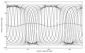
The path followed by the Planck spin axis is defined with respect to the Ecliptic plane. It corresponds to a motion in longitude which maintains an anti-Sun pointing (about one degree per day), to which is added a cycloidal motion (precession) of the spin axis around the anti-Sun position (fiducial point). The cycloidal path is defined by the following functions:
$ λ = θ sin((-1)^n ω (t-t_0)+φ) $ (eq. 1)
$β = -θ cos((-1)^n ω(t-t_0) + φ) $ (eq. 2)
where λ is the angular distance from the fiducial point in Ecliptic longitude, β the angular distance from the fiducial point in Ecliptic latitude, θ the spin axis precession amplitude, ω the pulsation of the precession, φ its phase, n the parameter which controls the motion direction of the precession, t is the time, and $t_0$ is the first time during the Planck survey at which the fiducial point crosses the 0 Ecliptic longitude line.
The reasons to decide to use such a precession of the spin axis are the following :
- An excursion of the spin axis from the anti-Sun direction is required to fully observe the whole sky (no excursion would leave a large area unobserved around the Ecliptic poles)
- The precession motion allows to keep the Sun aspect angle constant during the whole survey, therefore minimizing the thermal constraint variations on the spacecraft
The following precession parameters have been chosen for the BSS:
- amplitude $θ = 7.5^o$ (this value is the lowest possible which allows to cover the whole sky with all detectors)
- n = 1 (anti-clockwise motion as seen from the Sun)
- pulsation ω = 2π / (half a year). Faster precession was considered, and has interesting advantages, but is not possible given the constraints if one wants to keep a 7.5 deg. amplitude (which is necessary to cover the whole sky).
- The phase of the precession was decided according to this set of criteria (in order of importance):
a) respecting the operational constraints,
b) allowing the largest possible angle between two scans on the Crab,
c) avoiding null dipole amplitude for the whole mission,
d) optimizing the position of the planets in the beginning of the survey and with respect to the feasibility of their recovery,
e) placing the two “deep fields” where Galactic foregrounds are minimum,
f) allowing a reasonable survey margin (i.e. the time allowed to recover lost pointings if a problem occurs)
The phase is 340 deg. for Surveys 1 to 4, and 250 deg. for Surveys 5 to 8.
The scanning strategy for the second year of Routine Operations (i.e. Surveys 3 and 4) is exactly the same as for the first year, except that all pointings are shifted by 1 arcmin along the cross-scanning direction, in order to provide finer sky sampling for the highest frequency detectors when combining two years of observations.
The change of phase between Survey 4 and Survey 5 occurred because it was found essential especially on the HFI side that scanning direction crossings are increased in the Planck survey. By choosing a phase 90 deg. away from the original one, one optimizes the scanning strategy in this respect.
The details of the justifications for these parameters can be found in PL-WG9-TN-001.
The scanning strategy parameters are input to the PSO Survey Planning and Performance Tool, which is the software which generates the series of pointing records to be sent out to MOC for implementation.
An approximate visualisation of the Planck scanning strategy can be found here and here.
Spin axis manoeuvres and exact pointings[edit]
The motion of the spin axis is not continuous. Every change in the spin axis position is initiated by a manoeuvre which requires less than 5 minutes time to complete.
The duration between spin-axis manoeuvres is hereafter referred to as “dwelling times"; and the angular distance between manoeuvres along the spin axis path is hereafter referred to as “spacing”.
The dwelling times and spacings are defined as follows:
- The spacings are fixed to 2’ which roughly corresponds to Nyquist criterion for sampling the highest-frequency HFI detectors.
- The dwell times vary from 2360 s to 3904 s.
The exact series of coordinates and dwell times are set by equations 1 and 2 when one has fixed the spacings.
Data gap recoveries[edit]
Gaps in the data flow can occur because of various reasons:
- Anomalies may occur at spacecraft or instrument level, but also due to failures in the ground-to-spacecraft link or the ground segment itself. The adverse effects of such anomalies may be the loss of scientific data corresponding to one or several planned pointings, which have either not been acquired and/or stored in memory.
- Failure to acquire proper scientific data may occur to one or both instruments
In case a gap occurs, scientific criteria are applied to decide whether to recover the data through the Small-Gap Recovery procedure.
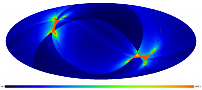
The Small-Gap Recovery (SGR) procedure can be applied by MOC or PSO:
- MOC-triggered SGR: Within its nominal scheduling procedure for an OD, the MOC searches the PPL for PREF corresponding to the OD being processed and any pointings which are subject of a Small Gap Recovery. As the PREF are sorted in chronological order according to their nominal start time, those corresponding to a small gap will naturally be the earliest. After checking attitude constraints, all observable pointings are listed and their dwell times reduced (initially) to the Minimum Dwell Time (MDT) as given in the PPL.
Having included all valid PREF the required slew times are calculated. With the required slew times and minimum dwell times for all pointings, the OD schedule may be under-populated; in this case the dwell times of all scheduled pointings will be increased equally to make use of all available time in the OD. If the resulting schedule is over-populated, even with MDT for all pointings, the recovery cannot be constrained to a single OD. The sequence of pointings for the ODs involved will be optimized in PREF scheduling and dwell times in order to effect the recovery and revert to the nominal timeline as quickly as possible.
- PSO-triggered SGR:
PSO declares a small gap when pointings that have been executed result in data of insufficient quality or inadequate frequency coverage. This assessment is based on data quality and instrument health information provided by the DPCs. The algorithm that is used by the PSO to check the scientific validity of a pointing is implemented within the SPPT software tool. The SPPT ingests on a weekly basis a Weekly Health Report (WHR) for the HFI and LFI containing information on the current working status of each detector and their expected condition over the next four weeks. On a daily basis, a Daily Quality Report (DQR) provided by the DPCs for both instruments, includes a set of parameters that describe the quality of the detection achieved by each individual detector for every pointing executed.
The scheme for declaring a Small-Gap Recovery from PSO is the following:
- If a pointing fails to meet the chosen requirement, it becomes an SGR candidate
- If there are at least 12 consecutive pointings which are declared SGR candidates, and the problem has been identified and solved, then an SGR is triggered Recoveries are only carried out if the recovery slewing out is guaranteed to be in OCM. MOC carries out this analysis and decides whether they perform the SGR accordingly.
- The start and end times of the gap and the list of the pointing numbers (or just the numbers of the first and last pointings to be recovered) are then sent to MOC by E-mail, with the notification to start a Small-Gap Recovery
- MOC implements the Small-Gap Recovery, provided the pointings can still be scheduled with respect to their latest start time, using the same scheme as described in the MOC-triggered SGR section
Throughout the Planck mission, data losses have been very rare. Small-Gap Recovery has been applied only a couple of times.
Special observations[edit]
The special observations are:
- normal scanning on Solar System objects for calibration purposes
This concerns the following objects (planets): Mars, Jupiter, Saturn, Uranus and Neptune whose thermal emission in the far-infrared and their point-source-like quality make them essential calibrators for spider-web bolometers and radiometers.
Mars is a particularly interesting calibrator for Planck because of its proper motion. However this proper motion makes it difficult to observe it many times during the mission.
Jupiter is the brightest source for (non-polarized) calibration. Saturn is also used a lot, and Uranus and Neptune are secondary calibrators.
- normal scanning on other (non-moving) sources for calibration purposes
This concerns mostly the Crab Nebula for polarizer calibration purposes. This supernova remnant is highly polarized and as such represents the main polarization calibrator for Planck.
- special pointings during the calibration phase, not relative to celestial sources
- "deep rings" : these special observations are performed on each passage of Jupiter and the Crab Nebula, from January 2012 onward.
They consist of very deeply sampled observations (0.5') with the spin axis along the Ecliptic plane, during typically two to three weeks.
These observations benefit from special relaxing of the celestial constraints with Solar Aspect Angles < 9 deg. rather than < 8 deg. during cycloidal surveying.
- "drift scans" : these special observations are performed on Mars, making use of its proper motion
Start and end of surveys[edit]
The completion of a given “survey” is declared when the logical AND of all frequency-coverage maps is greater than 95 %, OR the sky has been surveyed over a consecutive period of 7.5 months. Note that this definition is that of the Project Scientist and Planck Science Office. Data Processing Centres do not use the same concept of surveys to create "survey" maps.
In practice, since the gaps during the surveys have always been very small, it results in ~ six months per survey.
- Survey 1: starts August 13, 2009, ends Feb. 13, 2010
- Survey 2: starts Feb. 14, 2010, ends Aug. 13, 2010
- Survey 3: starts Aug. 14, 2010, ends Feb. 13, 2011
- Survey 4: starts Feb. 14, 2011, ends July 29th, 2011
This survey was shortened in ordered to start earlier with the new scanning strategy (see above).
- Survey 5: starts July 29th, 2011, ends January 30th, 2012
- Survey 6 (LFI only): starts January 30th, 2012, ends July 31st, 2012
- Survey 7 (LFI only): starts July 31st, 2012, ends January 31st, 2013
- Survey 8 (LFI only): starts February 1st, 2013, ends August 1st, 2013
Completion of full sky coverage during Surveys 1-2[edit]
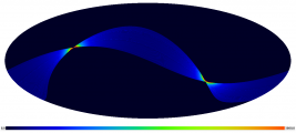
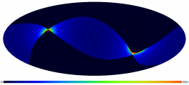
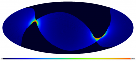
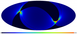
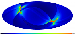
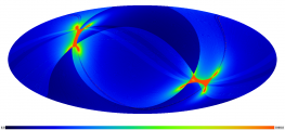
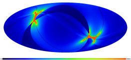
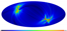
The picture gallery below exhibits the progress of sky coverage during the first months of survey (black color = unobserved areas).
- The HFI 353 GHz integration time after N months of survey. Unit is seconds per square degree, normalized to one detector.
Main planet and Crab observations during Surveys 1-7[edit]
Solar System objects and the Crab Nebula have been observed many times during the Planck surveys. Here is a complete list of these observations. Note that the deep rings and drift scans (Mars only) are in boldface.
- Crab: Sept. 16-22, 2009
- Mars: Oct. 17-29, 2009
- Jupiter: Oct. 25 – Nov. 1, 2009
- Neptune: Nov. 1-8, 2009
- Uranus: Dec. 6-16, 2009
- Saturn: Jan. 2-8, 2010
- Crab: March 6-12, 2010
- Mars: April 9-18, 2010
- Neptune: May 15-23, 2010
- Saturn: June 13-22, 2010
- Uranus: June 27 – July 5, 2010
- Jupiter: July 1-9, 2010
- Crab: Sept. 15-21, 2010
- Neptune: Nov. 3-11, 2010
- Jupiter: Dec. 9-18, 2010
- Uranus: Dec. 12-21, 2010
- Saturn: Jan. 15-22, 2011
- Crab: March 7-12, 2011
- Neptune: May 18-26, 2011
- Saturn: June 30 - July 9, 2011
- Uranus: July 3-11, 2011
- Jupiter: Aug. 9-15, 2011
- Crab: Sept. 10-18, 2011
This Crab scan was performed with the 250 deg. phase cycloidal strategy.
- Crab: Sept. 20-23, 2011
This Crab scan was performed with the 340 deg. phase cycloidal strategy.
- Mars: Dec. 8-16, 2011 ("drift scan": Mars is let move through the Planck focal plane via its proper motion)
- Mars: Dec. 17-26, 2011 (normal scanning)
- Jupiter: Jan. 8-30, 2012 (deep ring)
- Crab: Feb. 26 - March 16, 2012 (deep ring)
- Jupiter: Sept. 1-14, 2012 (deep ring)
- Crab: Sept. 14 - Oct. 1, 2012 (deep ring)
- Neptune: Nov. 19-27, 2012
- Uranus: Dec. 24-30, 2012
- Saturn: Jan. 30 - Feb. 5, 2013
- Jupiter: Feb. 2013 (deep ring)
Resulting integration time distribution[edit]
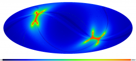
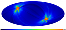
The integration time after the end of HFI operations (January 2012) is shown in the following picture gallery.
Units are seconds per square degree, normalized to one detector, for all maps. The projection is full-sky Mollweide centered on the Galactic Centre.
- Integration time after the end of HFI operations (January 2012). Units are seconds per square degree, normalized to one detector.
References[edit]
- ↑ Planck early results. I. The Planck mission, Planck Collaboration I, A&A, 536, A1, (2011).
- ↑ Scanning strategy for mapping the Cosmic Microwave Background anisotropies with Planck, X. Dupac, J. Tauber, A&A, 430, 363-371, (2005).
- ↑ Planck pre-launch status: The HFI instrument, from specification to actual performance, J.-M. Lamarre, J.-L. Puget, P. A. R. Ade, F. Bouchet, G. Guyot, A. E. Lange, F. Pajot, A. Arondel, K. Benabed, J.-L. Beney, A. Benoît, J.-P. Bernard, R. Bhatia, Y. Blanc, J. J. Bock, E. Bréelle, T. W. Bradshaw, P. Camus, A. Catalano, J. Charra, M. Charra, S. E. Church, F. Couchot, A. Coulais, B. P. Crill, M. R. Crook, K. Dassas, P. de Bernardis, J. Delabrouille, P. de Marcillac, J.-M. Delouis, F.-X. Désert, C. Dumesnil, X. Dupac, G. Efstathiou, P. Eng, C. Evesque, J.-J. Fourmond, K. Ganga, M. Giard, R. Gispert, L. Guglielmi, J. Haissinski, S. Henrot-Versillé, E. Hivon, W. A. Holmes, W. C. Jones, T. C. Koch, H. Lagardère, P. Lami, J. Landé, B. Leriche, C. Leroy, Y. Longval, J. F. Macías-Pérez, T. Maciaszek, B. Maffei, B. Mansoux, C. Marty, S. Masi, C. Mercier, M.-A. Miville-Deschênes, A. Moneti, L. Montier, J. A. Murphy, J. Narbonne, M. Nexon, C. G. Paine, J. Pahn, O. Perdereau, F. Piacentini, M. Piat, S. Plaszczynski, E. Pointecouteau, R. Pons, N. Ponthieu, S. Prunet, D. Rambaud, G. Recouvreur, C. Renault, I. Ristorcelli, C. Rosset, D. Santos, G. Savini, G. Serra, P. Stassi, R. V. Sudiwala, J.-F. Sygnet, J. A. Tauber, J.-P. Torre, M. Tristram, L. Vibert, A. Woodcraft, V. Yurchenko, D. Yvon, A&A, 520, A9+, (2010).
(Planck) Low Frequency Instrument
revolutions per minute
(Planck) High Frequency Instrument
Planck Science Office
[ESA's] Mission Operation Center [Darmstadt, Germany]
Small Gap Recovery
Operation Day definition is geometric visibility driven as it runs from the start of a DTCP (satellite Acquisition Of Signal) to the start of the next DTCP. Given the different ground stations and spacecraft will takes which station for how long, the OD duration varies but it is basically once a day.
Pre-programmed Pointing List
Survey Performance and Planning Tool
Weekly Health Report
Daily Quality Report
[LFI meaning]: absolute calibration refers to the 0th order calibration for each channel, 1 single number, while the relative calibration refers to the component of the calibration that varies pointing period by pointing period.
