Difference between revisions of "HFI cold optics"
(→Reference Bolometer Spectra) |
(→Waveguide Model) |
||
| Line 157: | Line 157: | ||
where <math>\sigma</math> is the frequency in cm<math>^{-1}</math>, <math>r_w</math> is the waveguide radius in cm, <math>l_w</math> is the waveguide length in cm, and <math>c_{nm}</math> is a waveguide specific constant; 1.841 for the TE<math>_{11}</math>/TM<math>_{11}</math> (HE<math>_{11}</math>) hybrid mode in this case . Table [tab:WG] lists the waveguide radii and lengths resultant from the waveguide model fit to the ratioed spectra. As all of the feedhorns for a given band are meant to be identical (i.e. within mechanical manufacturing tolerances) the uncertainty of the waveguide transmission is estimated statistically using all of the waveguide models for each band. I.e. for <math>n</math> bands, the uncertainty at each spectral data point is determined by the standard deviation of <math>n</math> transmission values at that frequency. As a result of each detector in a given band having a unique cut-on frequency, this method begins to over-estimate the uncertainty for frequencies approaching the cut-on; for regions very near the waveguide cut-on, the uncertainty is extrapolated from the ratioed spectrum as a more accurate representation. | where <math>\sigma</math> is the frequency in cm<math>^{-1}</math>, <math>r_w</math> is the waveguide radius in cm, <math>l_w</math> is the waveguide length in cm, and <math>c_{nm}</math> is a waveguide specific constant; 1.841 for the TE<math>_{11}</math>/TM<math>_{11}</math> (HE<math>_{11}</math>) hybrid mode in this case . Table [tab:WG] lists the waveguide radii and lengths resultant from the waveguide model fit to the ratioed spectra. As all of the feedhorns for a given band are meant to be identical (i.e. within mechanical manufacturing tolerances) the uncertainty of the waveguide transmission is estimated statistically using all of the waveguide models for each band. I.e. for <math>n</math> bands, the uncertainty at each spectral data point is determined by the standard deviation of <math>n</math> transmission values at that frequency. As a result of each detector in a given band having a unique cut-on frequency, this method begins to over-estimate the uncertainty for frequencies approaching the cut-on; for regions very near the waveguide cut-on, the uncertainty is extrapolated from the ratioed spectrum as a more accurate representation. | ||
| − | + | A table of the waveguide fit parameters for each HFI detector is provided [[HFIspecWG|here]]. | |
| − | |||
| − | |||
| − | |||
| − | |||
| − | |||
| − | |||
| − | |||
| − | |||
| − | |||
| − | |||
| − | |||
| − | |||
| − | |||
| − | |||
| − | |||
| − | |||
| − | |||
| − | |||
| − | |||
| − | |||
| − | |||
| − | |||
| − | |||
| − | |||
| − | |||
| − | |||
| − | |||
| − | |||
| − | |||
| − | |||
| − | |||
| − | |||
| − | |||
| − | |||
| − | |||
| − | |||
| − | |||
| − | |||
| − | |||
| − | |||
| − | |||
| − | |||
| − | |||
| − | |||
| − | |||
| − | |||
| − | |||
| − | |||
| − | |||
| − | |||
| − | |||
| − | |||
| − | |||
| − | |||
| − | |||
| − | |||
| − | |||
| − | |||
| − | |||
| − | |||
| − | |||
| − | |||
| − | |||
| − | |||
| − | |||
| − | |||
| − | |||
| − | |||
| − | |||
| − | |||
| − | |||
| − | |||
| − | |||
| − | |||
| − | |||
| − | |||
| − | |||
| − | |||
| − | |||
| − | |||
| − | |||
| − | |||
| − | |||
| − | |||
| − | |||
| − | |||
| − | |||
| − | |||
| − | |||
| − | |||
| − | |||
| − | |||
| − | |||
| − | |||
| − | |||
| − | |||
| − | |||
| − | |||
| − | |||
| − | |||
| − | |||
| − | |||
| − | |||
| − | |||
| − | |||
| − | |||
| − | |||
| − | |||
=== Optical Efficiency === | === Optical Efficiency === | ||
Revision as of 12:56, 7 February 2013
(Lamarre)
Contents
- 1 Horns,lenses and filters
- 2 Spectral response
- 2.1 Additional Experiments
- 2.2 Filter Measurements
- 2.3 Data Processing and Fourier Transformation
- 2.4 Reference Bolometer Spectra
- 2.5 Out-of-Band Spectral Transmission Content
- 2.6 Waveguide Model
- 2.7 Optical Efficiency
- 2.8 CO interpolation
- 2.9 Spectral Response Conclusions and Conformity With Requirements
Horns,lenses and filters[edit]
links to Peter's paper
Feed horns beams (sub-system level)[edit]
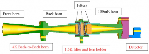
In order to meet with straylight, beam shapes and filtering requirements, a design using feedhorn coupled detectors has been chosen, with a triple horn configuration (see Figure 3.1.1). A detailed description of the HFI optical design and beam performances is given in Maffei et al.(2009) and Ade et al.(2009).
Single-moded horns patterns[edit]
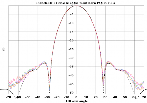
The spectral and geometrical properties of the horns have been characterized individually. The measured beam pattern of a typical front horn is compared with the prediction from the design (figure 3.1.2). The fit is excellent down to very low levels, which validates the logics that prevailed for characterizing the horns: modelling and optimizing the horns before implementation. Validating the model with a complete measurement of the beam intensity patterns.
For the single-moded horns, a method has been developed to use the measured intensities, together with the phase information from modeling to derive “worst-case” horn beam patterns that can be used in GRASP simulations of the telescope beams (phase information is mandatory). Worst-case beam patterns have been computed for all single-moded HFI horn types. A .pdf file (IAS-FN-WCB-001-03022009) detailing the algorithm can be found on the optics ftp site at ctwg1.planck.fr, in the following directory: /File_Exchange_Box_GOPT/Files_from_FN/Worst_case_beams”
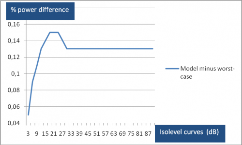
As an example, in Figure 3.1.3, we show the difference in encircled powers at constant isolevel intervals for the HFI 143_1a channel main beam using both the model and worst-case horns.
Ideal Multi-moded horns simulations[edit]
In the high frequency 545GHz and 857GHz Planck pixels both the back-to-back (BTB) horn and the detector horn have overmoded waveguide filters. The waveguide-horn structures are modelled using the scattering matrix approach used for the single-moded-CMB-channel horns, with the inclusion of modes of azimuthal orders, n = 0, 1, 2, 3 and 4. We assume reciprocity, and that the cavity plus cavity horn and filter behaves like a black-body: since the waveguide filter in the detector horn is wider than that of the BTB, it is reasonable to assume that any mode that can propagate through the BTB filter also propagates through the detector horn filter from the cavity. Thus, as far as the beam patterns are concerned the BTB is effectively coupled to a black body cavity also and all modes are excited at the back end of the BTB horn. Thus, all waveguide modes are equally excited in power but are also independent of each other so there is no phase relationship between them. Many of these modes may contribute independently (i.e. incoherently) to the beam on the sky. All coherent aperture fields have to be independently propagated through the PLANCK telescope.
From the S21 transmission scattering matrix for the whole BTB we recover the group of true independent hybrid fields that are transmitted by the waveguide filter and horn at the aperture of the BTB. These hybrid fields propagate independently through the telescope and onto the sky at a single frequency. The beam pattern for the band is obtained by adding the filter transmission weighted coherent fields in quadrature across the band (Microwave Horns and Feeds A. David Olver, Institution of Electrical Engineers) (“Shaped Corrugated horns for Cosmic Microwave Background Anisotropy Measurements” B. Maffei, P.A.R. Ade, C.E. Tucker, E. Wakui, R.J. Wylde, J.A. Murphy, R.M. Colgan, Int Jour Infrared & Millimeter waves, 21, (12) 2023-2033, December 2000).
Far field patterns of horns and comparison with test data:
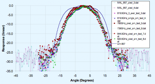
The far-field patterns of the horns (which illuminate the Planck mirrors) have been simulated and are shown in figure 3.1.4a for a few spot frequencies across the 857 GHz band. Note that the edge taper is approx -30dB at 25 degrees as required at the centre of the band. Superimposed is the broadband measurement made at Cardiff (see below) which clearly looks narrower than the majority of the spot frequency measurements and requires explanation. The measured far field beam patterns across the band are narrower than the predicted far field beams right across the band. The simulated beams are too wide suggesting missing higher order modes, either due to attenuation between the cavity and the BTB, or to the experimental setup. Away from the band centre the theoretical beams also appear to be too wide, indicating missing modes (see figure 3.1.4b).
Grouping contributions according to azimuthal order and overlaying the measurement data to investigate missing field distributions, modes of order 2 and higher appear to be absent. The beam containing modes of azimuthal orders n = 0 and 1 appears to fit the measured beams reasonably. Adding modes with azimuthal order n = 2 gives a simulated beam that is too wide, suggesting that these modes are absent from the measured BTB front aperture field.
Spectral response[edit]
(Spencer) This section is comprised of excerpts from the HFI - Spectral Calibration report of the IAS measurements, v3.02, an internal report describing detailed pre-flight ground based measurements of the HFI focal plane. The experimental setup, data collection, and related data processing are described. The official version of the HFI detector spectral transmission profiles is available within the HFI instrument model and the RIMO files in the Planck Legacy archive [ref.] . This data is comprised of broadband Fourier transform spectrometer (FTS) measurements conducted with the HFI focal plane assembly in a ground-based test cryostat, and includes a waveguide model for the low frequency spectral region, and component-level filter spectra for the remaining out of band spectral regions. Specific attention is given to in-band and near-band spectral regions surrounding CO rotational transitions in order to support the CO extraction component separation effort [ref.] . The spectral transmission profiles are evaluated with parameters such as cut-on, cut-off, centre frequency, effective frequency (including spectral index), and band-width, all provided in this analysis. Further evaluation yields band-average spectra ( [ref.] ) and unit conversion / colour correction coefficients ( [ref.] ) and software routines to generate additional unit conversion and colour correction coefficients ( [ref.] ).
The main goal of the spectral transmission tests of the HFI instrument is to measure the spectral response of all HFI detectors to a known source of EM radiation individually. This was determined by measuring the interferometric output of all detection channels for radiation propagated through a continuously scanned polarising Fourier transform spectrometer (FTS). The required accuracy to which the spectral transmission is to be recovered is 1. It is important to note that the absolute spectral calibration cannot be achieved solely from the analysis of the FTS data because of uncertainties in the coupling efficiency of the FTS source through the FTS, input optics, and integrating sphere. The relative FTS measurements must be combined with the optical efficiency tests which used internal black-body sources (EFF Test – see §EFF). A reference bolometer located in an intermediate integrating sphere (accepting sr of incident radiation) within the FTS test setup was used to ratio the HFI detector spectra against to determine the throughput-normalized relative transmission spectra for each HFI detector. Data were collected over a series of pre-flight test campaigns, and processed/analyzed using standard Fourier data processing techniques.
Additional Experiments[edit]
There were two significant additional tests that are used in the derivation of the HFI detector spectral transmission profiles beyond the scope of the IAS HFI FTS measurements. Additional filter measurements were recorded in the Astronomical Instrumentation Group (AIG) test facility at Cardiff during filter stack production. These measurements are used to extend the IAS FTS spectral measurements beyond the HFI spectral passband. The EFF tests are used to obtain optical efficiency parameters for each detector. These parameters, when combined with the respective normalized spectral transmission profiles, provide an estimate of the absolute spectral transmission. The EFF tests are discussed in greater detail by A. Catalano ( [ref.] ). The filter measurements are described in §filter below.
Filter Measurements[edit]
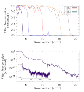
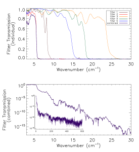
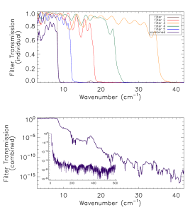
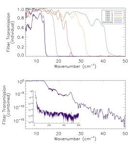
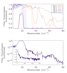
Prior to the IAS measurements with the integrated HFI detectors and filter stacks, FTS measurements of the individual filters comprising the filter stacks for each band were conducted at Cardiff. As will be discussed in §[sec:OOB], the independent measure of the filter stack transmission is used for a portion of the HFI detector spectral transmission for regions of the spectrum where it is deemed to be of better quality than the IAS FTS measurements (i.e. for frequencies outside of the band edge filter cut-off(s)). The filter stacks for each of the frequency bands are comprised of 5 filters. There is an additional low frequency cut-on filter for the 545 and 857 GHz bands as the waveguide cut-on is too low for these multi-moded channels. Figures [fig:Filt100] – [fig:Filt857] show the individual filter transmission measurements as well as the combined filter stack product.
- Combined (bottom) and individual (top) filter transmission measurements for the 5 filters within the HFI band filter stacks (6 for 545 and 857 GHz).
The uncertainty on the combined filter transmission measurement is determined as follows. Let represent the individual filter transmission. The standard deviation of all values of below a threshold of is used as an approximate uncertainty for each individual filter measurement, i.e. . The individual uncertainty estimates are combined to provide an estimate of the combined filter transmission spectral uncertainty through standard error propagation. For the combined filter transmission represented as , the associated uncertainty estimate is given as
Data Processing and Fourier Transformation[edit]
Having identified the data sections that are of interest, here follows the data processing sequence used to obtain the resulting spectra. The processing steps taken are as follows:
- Selection and extraction of time sampled data sets
- Conversion of time sampled data to arrays of OPD sampled interferogram data sets
- Fourier transformation and averaging of interferogram data sets
- Discrimination of poor quality spectra by standard deviation comparison (see §[sec:FTavg])
- Division of detector spectra by reference bolometer spectra to obtain normalized spectral transmission profiles
- Combination of relative transmission spectra with filter measurements and waveguide models
- Determination of optical efficiency through evaluation of normalized spectral transmission in the context of the EFF experiments
- Addition of over-sampled data into spectrum for the CO transition regions (see §[sec:CO])
- Identification of common frequency sampling per channel and interpolation of spectra onto the common sampling
Further details regarding the interferogram processing are provided here.
Reference Bolometer Spectra[edit]
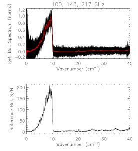
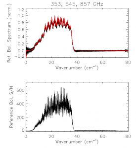
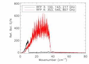
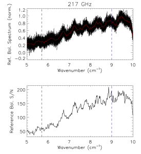
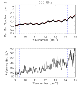
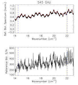
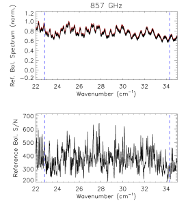
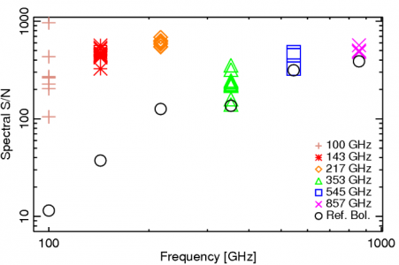
The reference bolometer spectra are obtained in a fashion similar to that used for the HFI detectors. Wherever possible, the same data processing is applied to the reference bolometer data as was applied to the HFI detector data, including optical filtering, scan speed, scan length, source intensity, apodization, phase correction, etc. Table [tab:Brefstats] contains the reference bolometer data set properties corresponding those listed for the HFI detectors in Table [tab:Igstats]. Figures [fig:BrefL] - [fig:Bref857] illustrate the resultant spectra and S/N from the reference bolometer data sets. Figure [fig:SNall] compares the approximate S/N of the average spectrum for each detector against the reference bolometer average spectrum S/N over the same spectral region.
| Band (GHz) | # Ifgm. | # Spec. | MPD (cm) | ILS (cm) | avg. S/N |
| 100 | 164 | 164 | 29.644698 | 0.020357772 | 11.478057 |
| 143 | 164 | 164 | 29.644698 | 0.020357772 | 37.361317 |
| 217 | 164 | 164 | 29.644698 | 0.020357772 | 126.14280 |
| 353 | 24 | 24 | 29.652306 | 0.020352549 | 136.06159 |
| 545 | 24 | 24 | 29.652306 | 0.020352549 | 314.58093 |
| 857 | 24 | 24 | 29.652306 | 0.020352549 | 388.23050 |
- Reference bolometer spectra and S/N.
- Reference bolometer spectra (top) and S/N (bottom) for each of the HFI bands (vertical bars represent band edges).
FIXME: This figure needs updated.
Out-of-Band Spectral Transmission Content[edit]
The HFI detector spectral transmission profiles have been extended beyond the optical pass-band of the detectors. This is done by using a combination of a waveguide model and external filter measurements for the out-of-band regions of the detector spectral response. An uncertainty estimate for these additional spectral regions is also provided, however, it should be noted that the spectral uncertainty for the waveguide and filter spectra are determined indirectly (as described above/below). There is a transition from IAS FTS data to filter data for every band edge which is defined by an optical filter. For the 100, 143, 217, and 353 GHz bands this is the high frequency cut-off band edge. For the 545 and 857 GHz bands a separate filter is used to define each of the high and low frequency band edges. For the spectral regions outside of the HFI detector optical bands, first the IAS FTS data is used to qualitatively verify that there are no spectral leaks or features, and then the external filter measurements are grafted into the ratioed spectra where they better represent the relative spectral transmission.
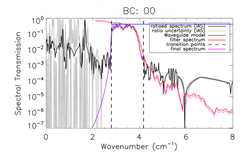
The normalized ratioed spectrum and filter are both scaled by the optical efficiency (see §[sec:EFF]). For the 100 - 353 bands, the filter spectrum is also scaled by to account for single-moded throughput normalization. This frequency scaling results in a more accurate in- and near-band match between the two sets of spectra, at the cost of less accuracy at much higher frequencies where any transmission will not be single-moded. As ransmission at higher frequencies is significantly reduced, this trade-off is acceptable. The 545 and 857 GHz bands have their filter spectra without the additional frequency scaling as this is not correct for multi-moded propagation. Both lower and upper frequency thresholds, , and , are defined for each band, below and above which the IAS-FTS spectra and/or the Cardiff composite filter spectra must be used, respectively. This is done to avoid introducing any detector nonlinearity residuals into the final spectral transmission data products. The region between these two points is defined as the transition region; within this region the amplitudes and slopes of the IAS and filter spectra are used to determine the spectral cross-oveer/transition point. Additional checks are performed to ensure that non-physical data processing artefacts are not introduced into the spectral transition region. Additionally, a similar technique is used, with decreasing frequency instead of increasing, for the 545 and 857 GHz bands with a filter-induced frequency cut-on. Figure [fig:OOBex] illustrates an example of both the FTS and filter spectra used in extending the transmission profiles beyond the HFI optical bands. Similar plots for every detector are shown in §[sec:stitch].
Waveguide Model[edit]
A waveguide model is used to provide the data for the lowest frequency portion of the HFI detector spectral transmission. For the 100, 143, 217, and 353 GHz bands the waveguide model is transitioned (with increasing frequency) to the FTS ratioed spectra directly. There is an intermediate transition to the filter data, and then the ratioed spectra for the 545 and 857 GHz bands. For each detector, the waveguide transmission, , is given by the following relation
where is the frequency in cm, is the waveguide radius in cm, is the waveguide length in cm, and is a waveguide specific constant; 1.841 for the TE/TM (HE) hybrid mode in this case . Table [tab:WG] lists the waveguide radii and lengths resultant from the waveguide model fit to the ratioed spectra. As all of the feedhorns for a given band are meant to be identical (i.e. within mechanical manufacturing tolerances) the uncertainty of the waveguide transmission is estimated statistically using all of the waveguide models for each band. I.e. for bands, the uncertainty at each spectral data point is determined by the standard deviation of transmission values at that frequency. As a result of each detector in a given band having a unique cut-on frequency, this method begins to over-estimate the uncertainty for frequencies approaching the cut-on; for regions very near the waveguide cut-on, the uncertainty is extrapolated from the ratioed spectrum as a more accurate representation.
A table of the waveguide fit parameters for each HFI detector is provided here.
Optical Efficiency[edit]
The EFF tests involved exposing the HFI detectors to a known blackbody source and observing the response. Sufficient details for the HFI detector spectral transmission profiles are provided here while full details of the EFF experiments and results are provided in a separate technical report . A blackbody source internal to the Saturne cryostat was set to a variety of temperatures (1 – 6 K) and the bolometer detector response was recorded. A bolometer model was applied to the recorded response in order to obtain the radiative optical power absorbed by the detector, in units of W, i.e. where represents the blackbody source temperature. Using the measured source temperature, the theoretical radiative optical power incident on the detector is also calculated using the Planck function. The ratio of the received power and the theoretical power provides the optical efficiency term. To remove any offsets in the measurement, a ratio of differences between unique temperature settings is used. The measured absorbed optical power difference is given by
where and represent two unique source temperature settings. The theoretical incident power is determined using the HFI detector spectral transmission profiles. Let represent the normalized detector transmission spectrum (i.e. it has been ratioed and had the waveguide model and filter data appropriately grafted). The spectral transmission is scaled for throughput and then re-normalized as follows
where is the division of by its maximum value, and is the speed of light. The normalized spectral transmission is then used with the Planck function at the temperature setting to determine the theoretical power, , as follows
where is the Planck constant, is the Boltzmann constant, the integration limits are given by and , and is the expected mode content of the frequency band. Table [tab:modes] lists the values used for each band . In this case the integration is performed over the range . The difference between the theoretical power loading is given by
which allows the optical efficiency term to be determined as follows
Thus, if were used in Equation [eq:EFFPth] in place of , the resultant optical efficiency would be unity, indicating that the transmission losses have already been taken into account.
The uncertainty estimate of the optical efficiency is statistically based on the results from the multiple temperature settings used in the EFF test sequences.
| Band (GHz) | 100 | 143 | 217 | 353 | 545 | 857 |
| 1 | 1 | 1 | 1 | 3.4 | 8.3 |
CO interpolation[edit]
The IAS FTS/Saturne data taken with the HFI detectors is limited to a spectral resolution of by the mechanical travel of the FTS translation stage. This corresponds to an unapodized FTS ILS FWHM of . The previous iteration of the spectral transmission (IMO ver. 2_28), in addition to a triangular apodization kernel, has a factor of 3 sub-sampled spectral resolution to improve the signal-to-noise ratio (S/N) of the output spectra. In light of the CO contribution to the 100 GHz spectra, the spectral transmission has been reprocessed at the original full spectral resolution with a different apodization function which provides better noise reduction and less spectral resolution degradation, as discussed above.
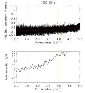
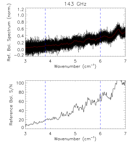
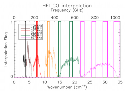
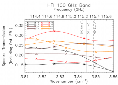
In order to provide an improved estimate of the spectral transmission near the CO features, an interpolation of the spectra by a factor of 10 has been performed. This over-sampling was accomplished by zero-padding the FTS interferograms prior to Fourier transformation , and subsequently incorporated into the Nyquist-sampled spectral data near the CO transitions (see Table [tab:CO]). Although the data are presented at higher resolution, the resolution of independent data points is not improved, i.e. the ILS line-width remains the same. A flag column has been added to the spectral transmission profile data files to indicate whether a given data point originates from the actual data, or is a result of the ILS-based interpolation. The region of the over-sampled, interpolated, data has been extended to also include other CO isotopes; the COJ1-0 – J9-8 transitions should be oversampled for CO, CO, CO, and CO. The original data points within the over-sampled region have been preserved (i.e. every tenth data point – the data point that is not an interpolated one – is flagged with a zero rather than a one), as is indicated by the data flag, so a flag filter on the data will restore the independent data points easily. Figure [fig:COflag] illustrates the regions where the over-sampling has been incorporated into the spectral transmission profiles. An example of the over-sampled spectra is shown in Figure [fig:COzoom100] for the 100 GHz detectors. Examples for the other detector bands are shown in §[sec:COappend]
| Band (GHz) | CO transition ( - ) | (GHz) | over-sampled region (GHz) |
| 100 | 1 – 0 | 115.2712018 | 109.67 – 115.39 |
| 143 | 1 – 0 | 115.2712018 | 109.67 – 115.39 |
| 143 | 2 – 1 | 230.5380000 | 219.34 – 230.77 |
| 217 | 2 – 1 | 230.5380000 | 219.34 – 230.77 |
| 353 | 3 – 2 | 345.7959899 | 329.00 – 346.15 |
| 545 | 4 – 3 | 461.0407682 | 438.64 – 461.51 |
| 545 | 5 – 4 | 576.2679305 | 548.28 – 576.85 |
| 857 | 6 – 5 | 691.4730763 | 657.89 – 692.17 |
| 857 | 7 – 6 | 806.6518060 | 767.48 – 807.46 |
| 857 | 8 – 7 | 921.7997000 | 877.04 – 922.73 |
| 857 | 9 – 8 | 1036.9123930 | 986.57 – 1037.95 |
| BC | Det. | CO transition () | Transmission | |
| 100 | 00 | 1a | 1 – 0 | 0.1495 0.0054 |
| 100 | 01 | 1b | 1 – 0 | 0.1812 0.0052 |
| 100 | 20 | 2a | 1 – 0 | 0.2577 0.0119 |
| 100 | 21 | 2b | 1 – 0 | 0.1944 0.0086 |
| 100 | 40 | 3a | 1 – 0 | 0.2798 0.0133 |
| 100 | 41 | 3b | 1 – 0 | 0.1660 0.0093 |
| 100 | 80 | 4a | 1 – 0 | 0.2538 0.0114 |
| 100 | 81 | 4b | 1 – 0 | 2173 0.0105 |
| 217 | 04 | 1 | 2 – 1 | 0.3781 0.0026 |
| 217 | 11 | 5a | 2 – 1 | 0.4530 0.0029 |
| 217 | 12 | 5b | 2 – 1 | 0.4174 0.0030 |
| 217 | 22 | 2 | 2 – 1 | 0.3773 0.0026 |
| 217 | 43 | 6a | 2 – 1 | 0.3149 0.0023 |
| 217 | 44 | 6b | 2 – 1 | 0.3609 0.0030 |
| 217 | 52 | 3 | 2 – 1 | 0.3924 0.0025 |
| 217 | 61 | 7a | 2 – 1 | 0.3428 0.0022 |
| 217 | 62 | 7b | 2 – 1 | 0.2770 0.0017 |
| 217 | 71 | 8a | 2 – 1 | 0.4623 0.0031 |
| 217 | 72 | 8b | 2 – 1 | 0.4340 0.0031 |
| 217 | 84 | 4 | 2 – 1 | 0.3506 0.0025 |
| 353 | 13 | 2 | 3 – 2 | 0.5461 0.0044 |
| 353 | 23 | 3a | 3 – 2 | 0.3443 0.0030 |
| 353 | 24 | 3b | 3 – 2 | 0.4706 0.0037 |
| 353 | 32 | 4a | 3 – 2 | 0.3099 0.0024 |
| 353 | 33 | 4b | 3 – 2 | 0.2801 0.0027 |
| 353 | 45 | 7 | 3 – 2 | 0.2923 0.0022 |
| 353 | 53 | 5a | 3 – 2 | 0.3150 0.0024 |
| 353 | 54 | 5b | 3 – 2 | 0.3181 0.0023 |
| 353 | 63 | 6a | 3 – 2 | 0.2059 0.0014 |
| 353 | 64 | 6b | 3 – 2 | 0.2113 0.0017 |
| 353 | 85 | 8 | 3 – 2 | 0.3509 0.0028 |
| 545 | 14 | 1 | 4 – 3 | 0.0747 0.0003 |
| 545 | 34 | 2 | 4 – 3 | 0.0731 0.0003 |
| 545 | 55 | 3 | 4 – 3 | 0.0521 0.0002 |
| 545 | 73 | 4 | 4 – 3 | 0.0473 0.0002 |
| 545 | 14 | 1 | 5 – 4 | 0.3306 0.0012 |
| 545 | 34 | 2 | 5 – 4 | 0.3183 0.0011 |
| 545 | 55 | 3 | 5 – 4 | 0.2428 0.0009 |
| 545 | 73 | 4 | 5 – 4 | 0.2597 0.0009 |
| 857 | 25 | 1 | 6 – 5 | 0.0280 0.0001 |
| 857 | 35 | 2 | 6 – 5 | 0.0241 0.0001 |
| 857 | 65 | 3 | 6 – 5 | 0.0292 0.0001 |
| 857 | 74 | 4 | 6 – 5 | 0.0159 0.0001 |
| 857 | 25 | 1 | 7 – 6 | 0.1636 0.0005 |
| 857 | 35 | 2 | 7 – 6 | 0.1427 0.0004 |
| 857 | 65 | 3 | 7 – 6 | 2176 0.0007 |
| 857 | 74 | 4 | 7 – 6 | 0.1168 0.0003 |
| 857 | 25 | 1 | 8 – 7 | 0.2554 0.0009 |
| 857 | 35 | 2 | 8 – 7 | 0.2218 0.0007 |
| 857 | 65 | 3 | 8 – 7 | 0.2744 0.0009 |
| 857 | 74 | 4 | 8 – 7 | 0.1119 0.0004 |
| 857 | 25 | 1 | 9 – 8 | 0.0053 0.0000 |
| 857 | 35 | 2 | 9 – 8 | 0.0060 0.0000 |
| 857 | 65 | 3 | 9 – 8 | 0.0085 0.0000 |
| 857 | 74 | 4 | 9 – 8 | 0.0001 0.0000 |
Spectral Response Conclusions and Conformity With Requirements[edit]
The two defining requirements indicated in the HFI calibration plan are the acquisition of the spectral transmission of the single pixels with a prescribed accuracy and spectral resolution. The desired accuracy is 3% for the low frequency channels (CMB – 100, 143, and 217 GHz) and 1% for the high frequency channels (353, 545, 857 GHz). The spectral resolution requirement is for a resolution superior to 0.1 cm.
The spectral resolution requirement has been exceeded by more than a factor of five. It is also possible to degrade the spectral resolution to the 0.1 cm requirement to gain an improvement in the S/N.
No quantitative number is present on the document regarding the blocking of high frequency (near IR, visible, UV) radiation outside the range of the instrument. Checks in order to quantify the rejection have been performed at subsystem level and estimates of the out-of-band transmission profiles have been incorporated into the data products. The high level of out-of-band signal attenuation is verified by in-flight observations as demonstrated in the Spectral Response paper ([ref.]).
Considering statistical fluctuations in the determination of the spectra, these goals have been achieved. There are, however, caveats regarding the nature of error bars when dealing with frequency space. The nature of uncertainties in spectra determination is less obvious than when dealing with timestream data. Systematic effects produced from instrumental setup, but also by data reduction can in some cases exceed the actual statistical oscillation in the determination of the final spectra. This is the case for the high-frequency data for instance where the statistical fluctuation of the different determinations of the spectra in some case are better than 1 part in .
A second caveat regards the method of data analysis of the calibration test data, for which the ratio with the reference bolometer data (of which the relative error is a function of frequency) introduces an error that increase with wavelength. With the spectral resolution of the data provided being much higher than the stated 0.1 cm, the transmission accuracy requirement is not met for the 100 GHz detectors. It is possible to degrade the spectral resolution to the 0.1cm level to allow the accuracy to achieve the required level, but the higher spectral resolution data has been provided to better assist with the CO contamination removal from the 100 GHz signal.
Figures containing the full spectral response of each HFI detector, and band-average spectra, are provided in the Appendix [ref.]. Details of the generation of band-average spectra, unit conversion coefficients, and colour correction coefficients are provided in the Data Processing sections of the Explanatory Supplement. IDL scripts have been provided alongside the PLA to allow users to generate unit conversion and colour correction coefficients; these are described in the PLA section [ref.].
(Planck) High Frequency Instrument
Back To Back HFI horns
Cosmic Microwave background
Instrument Line Shape
Full-Width-at-Half-Maximum
LFI Waveguide
Planck Legacy Archive

